Vehicle cover list
Vehicle |
Engine code |
Year |
LSU sensor |
Note |
Porsche 996 turbo |
M96/70 |
2001 - 2005 |
Uses stock LSU 4.2 sensors |
|
Note: Manual transmission only!
Control options
Only available as a MaxxECU PRO solution.
OEM options |
MaxxECU IO |
MaxxECU PRO |
Fuel pump |
GPO 5 |
Yes |
Tachometer |
Yes |
|
Error light |
Yes |
|
E-Throttle with cruise control |
GPO 11/12 |
Yes |
AC |
GPO 4 |
Yes |
OEM Boost solenoid |
GPO 1 |
Yes |
VarioCAM (VCT solenoid(s)) |
GPO 6/8 |
Yes |
Knock sensor(s) |
KNOCK1, KNOCK2 |
Yes |
OEM Engine fan |
GPO 2 |
Yes |
Vehicle speed |
DIN 2 |
Yes |
Clutch switch |
DIN 6 |
Yes |
AC request |
Yes |
|
EVAP |
INJ 15 |
Yes |
Airpump |
INJ 14 |
Yes |
Divertvalve |
INJ 13 |
Yes |
Secondary Air Valve |
INJ 12 |
Yes |
Engine compartment fan |
INJ 9 |
Yes |
Valvelift |
INJ 7 |
Yes |
Stock wideband lambdas |
WBO1/WBO2 |
Yes |
OEM coolant temp sensor |
CLT |
Yes |
OEM oil temp senspr |
AIN 1 |
Yes |
OEM engine compartment temp |
AIN 2 |
Yes |
Plugin adapter description
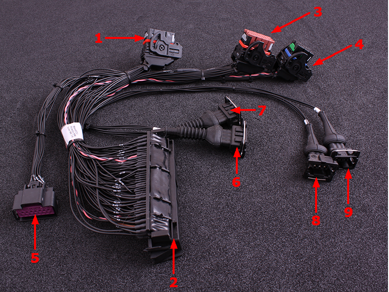
1 |
MaxxECU CMC connector 1 |
2 |
Vehicle harness adapter |
3 |
MaxxECU CMC connector 3 |
4 |
MaxxECU CMC connector 4 |
5 |
16-pin extra connector |
6 |
Ignition module connector |
7 |
Ignition module connector |
8 |
Ignition module connector |
9 |
Ignition module connector |
ECU location and installation
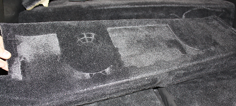
Stock ECU is located below rear seat.
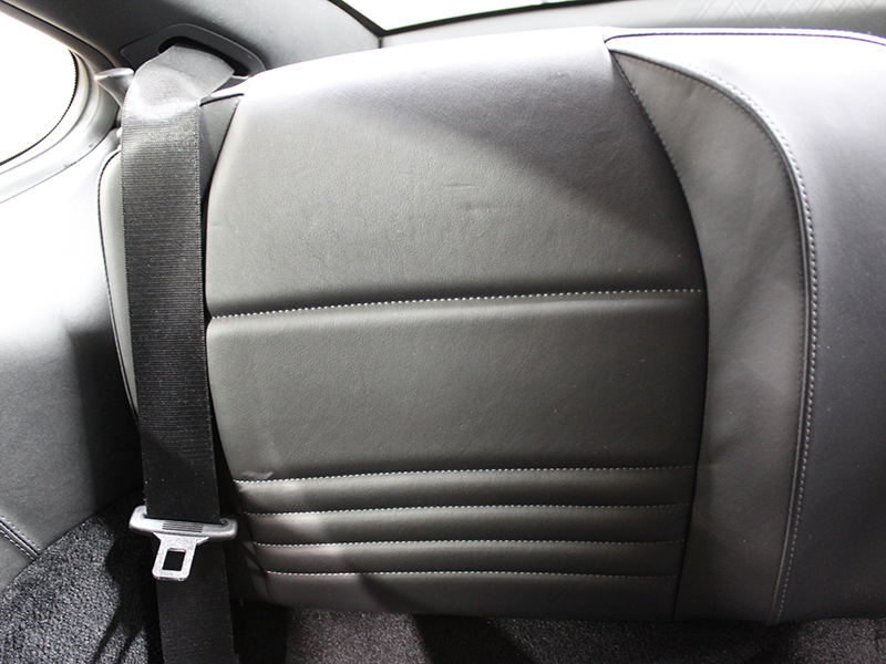
1. Remove rear seat.
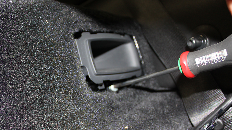
2. Remove plastic cover and remove screw on the soundsystem.
3. Remove sound woofer.
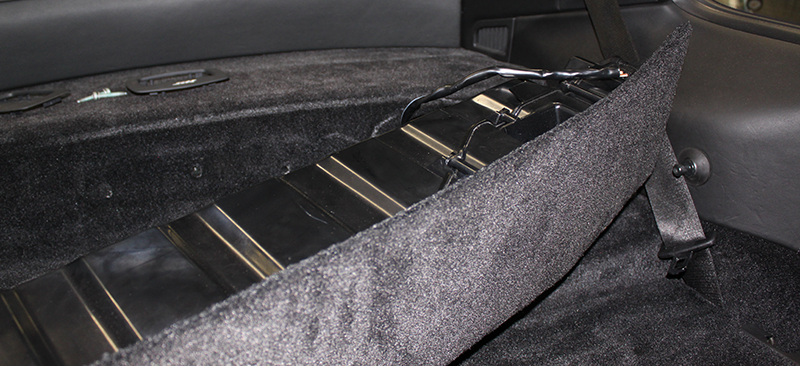
4. Remove.
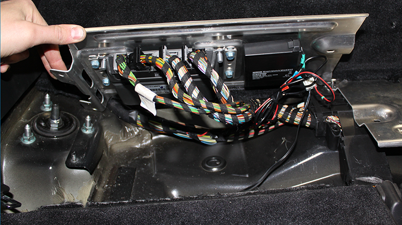
5. Remove and lift up the support brackets.
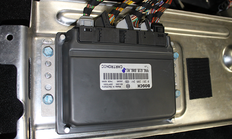
6. Remove ECU connectors from Stock ECU. We don't reuse the support bracket since it wont fit anymore.
Note: Please disconnect battery before removing stock ECU.
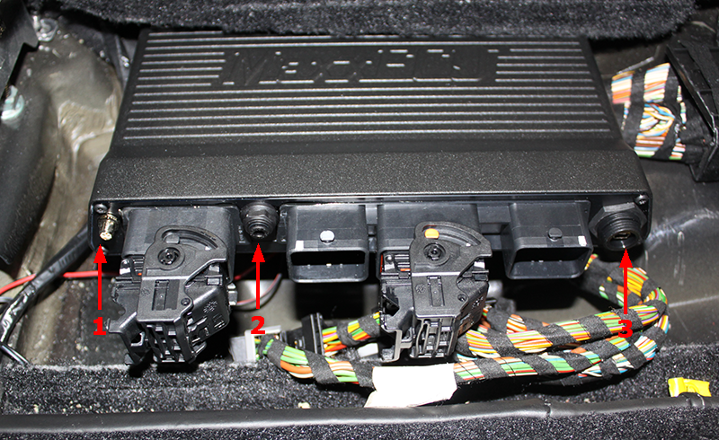
7. Connect the MaxxECU adapter harness in vehicle harness adapter and place the MaxxECU PRO unit above.
Don't forget to mount the included Bluetooth antenna (1), MAP-sensor hose (2) from intake and the USB cable (3) before
assembling rear seat.
Note: Preferable route the included MAP-sensor hose right next to stock engine harness and find a suitable vaccum/pressure line
available on your application (on our test vehicle we needed to remove E-Throttle body to find a good MAP point).
16-pin extra connector
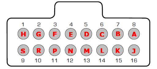
Note: Pinout is from the wire side of the pre-wired cable harness.
Pin |
Description |
Usage |
Note |
1 |
GPO 19 (+12V max 1.5A) |
||
2 |
GPO 20 (+12V max 1.5A) |
||
3 |
GPO 29 (GND) |
||
4 |
GPO 30 (GND) |
|
|
5 |
+5V sensor supply |
|
|
6 |
GPO 24 |
|
|
7 |
GPO 7/DIN 3 |
|
|
8 |
GPO 25 |
|
|
9 |
GPO 26 |
||
10 |
AIN 10 (0-5V) |
||
11 |
AIN 11 (0-5V) |
||
12 |
+12V |
Output |
|
13 |
GND |
|
|
14 |
Sensor GND |
|
|
15 |
AIN 3 (0-5V) |
||
16 |
AIN 4 (0-5V) |