Vehicle cover list
Vehicle |
Engine code |
Year |
LSU sensor |
Note |
Nissan Skyline R34 GT-R |
RB26 |
1998 - 2002 |
External sensor needed |
|
Note: Manual transmission only!
Control options
The MaxxECU adapter for Nissan Skyline R32/33 can be used MaxxECU V1, RACE or PRO.
Note: Currently there is no solution for MaxxECU STREET.
Options |
MaxxECU IO |
V1/RACE/PRO |
Fuel pump |
GPO 6 |
Yes |
Tachometer |
GPO 8 |
Yes |
Boost solenoid (OEM) |
GPO 4 |
Yes |
Vehicle speed |
DIN 1 |
Yes |
AC request |
DIN 2 |
Yes |
Check engine light |
GPO 5 |
Yes |
Idle solenoid |
GPO 3 |
Yes |
AC |
GPO 2 |
Yes |
Multi Function Display |
INJ 7 |
Yes |
Bluetooth (MDash) |
- |
Yes |
Knock sensor(s) |
- |
|
EGT option |
- |
Yes, direct |
Note: This plugin adapter uses only connector 1 on MaxxECU RACE/PRO units, for extra functionality, the second harness can be added to the RACE ECU.
The PRO ECU have in total of four ECU connectors which could be added for extra functionality: second harness, third harness and/or harness 4.
Plugin adapter description
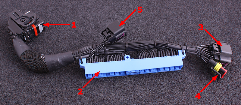
1 |
MaxxECU CMC connector 1 |
2 |
Vehicle harness adapter |
3 |
16-pin extra connector |
4 |
3-pin extra connector for ex. pressure sensor, analog input 4(AIN 4) |
5 |
4-pin connector for external amplifier (needed for the Multi Function Display), included in kit |
ECU location and installation
Stock ECU is located behind plastic guard on passenger side floor.
1.Remove the plastic guard where the ECU is located.
2.Disconnect battery from vehicle.
3.Remove and disconnect stock ECU from vehicle harness.
4.Install MaxxECU adapter harness.
5.Route the included MaxxECU MAP-sensor hose to the intake manifold and connect into the MaxxECU.
6.Route wide band lambda cables to exhaust system, install lambda sensor in exhaust and wire the lambda sensor as instructed below.
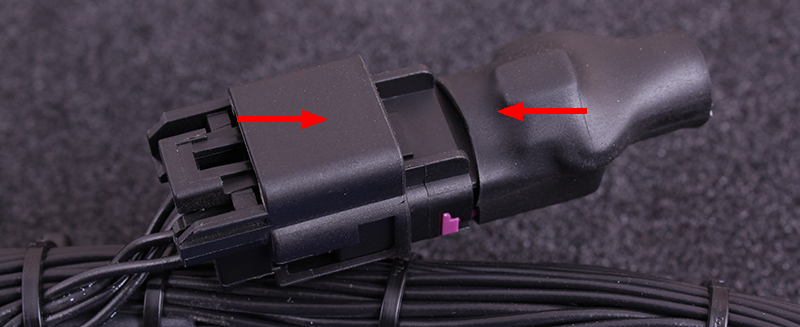
Attached the included 4-pin connector into the corresponding connector in harness.
Note: This connector might be pre-mounted from factory.
3-pin extra connector (0-5V analog input 4)
1 |
Sensor GND |
2 |
Analog input 4 (0-5v) |
3 |
+5V sensor supply |
see also, analog input.
16-pin extra connector
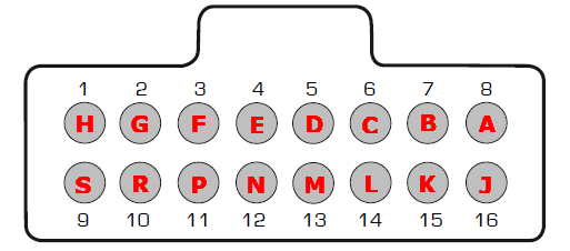
Note: Pinout is from the wire side of the pre-wired cable harness.
Pin |
Description |
Usage |
Note |
1 |
Wide band (VREF) |
|
|
2 |
Wide band (VS) |
|
|
3 |
Wide band (shield) |
|
|
4 |
Wide band (H-) |
|
|
5 |
GPO 7 / DIN 3 |
|
|
6 |
- |
|
|
7 |
- |
|
|
8 |
INJ 8 |
|
|
9 |
Wide band (IP) |
|
|
10 |
Wide band (RCAL) |
|
|
11 |
+12V |
Output |
|
12 |
+12V |
Output |
|
13 |
Engine GND |
|
|
14 |
AIN 1 |
||
15 |
AIN 2 |
||
16 |
AIN 3 |
4-pin connector (external amplifier for MFD)
A |
Amplified TPS signal out to MFD |
B |
+5V power sensor supply |
C |
TPS signal in |
D |
Signal GND |
3-pin extra connector (0-5V analog input 4)
1 |
Sensor GND |
2 |
Analog input 4 (0-5v) |
3 |
+5V sensor supply |
see also, analog input.
Internal wide band lambda (Bosch LSU 4.2) connection
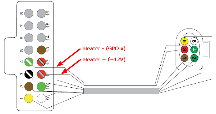
LSU 4.2 wiring with MaxxECU Plugin solutions.
Note: Seen from the wire side of the pre-wired connector.
PIN |
Function (LSU 4.2) |
1 |
VS |
2 |
RCAL |
3 |
+12V |
4 |
H- |
5 |
VREF |
6 |
IP |
See also external wide band lambda wiring.
See also
Example wirings of extra input and output