Trigger and synchronization issues are by far the most common cause of starting problems, misfires, unstable RPM, incorrect ignition timing, and lost sync events in aftermarket engine management systems.
The majority of reported issues such as no sync, intermittent sync loss, RPM dropouts, random misfires, timing drift, or erratic ignition behavior can be traced back to incorrect trigger configuration, mechanical instability of the trigger wheel, sensor-related problems, or poor signal integrity.
Reliable operation requires the crank trigger, cam/home signal, trigger wheel design, sensor type, air gap, mechanical mounting, and ECU trigger settings to function as a single, coherent system. Even small deviations in concentricity, material choice, sensor alignment, or mounting rigidity can result in synchronization errors, especially at higher RPM or load.
This section explains how trigger systems should be designed, installed, and verified, and highlights the most common causes of trigger and sync-related problems to ensure stable RPM detection, correct engine phase identification, and consistent fuel and ignition control.
MaxxECU needs a crankshaft trigger sensor to control fuel and ignition properly and the system needs to be aware of the type of trigger system being used.
Some trigger system also requires a HOME/CAM input to work, and in addition to for ex. a Missing tooth system, fuel and ignition can be sequential.
Wheels and triggers:
•Concentric (within 0.1mm(0.004").
•Robust trigger bracket.
•Trigger wheel not mounted on damper or other flexible material on crank.
•Made of magnetic material (steel, not stainless or aluminum), in order for the sensor to read it's tooth's.
•Use factory trigger setup if possible, except Nissan CAS or Mitsubishi EVO 4/2 which is not recommended for high horse applications.
MaxxECU has a built-in tools for trigger diagnostics:
• Trigger Oscilloscope <-- Please read and understand this tool before continuing.
• Trigger Logger <-- Please read and understand this tool before continuing.

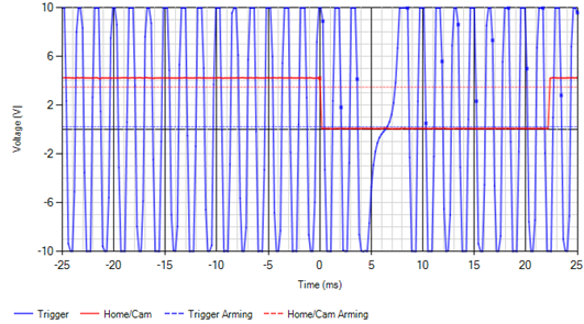
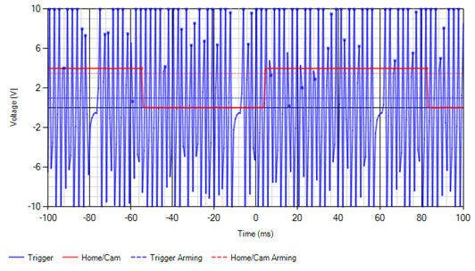
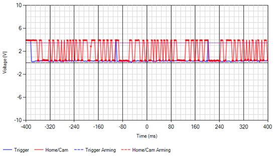
Trigger oscilloscope (Diagnostics --> Trigger oscilloscope)
This built-in feature indicates what MaxxECU "sees" in the trigger inputs.
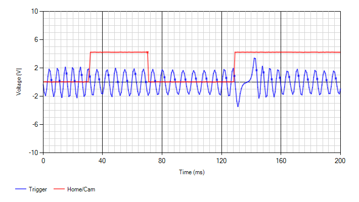
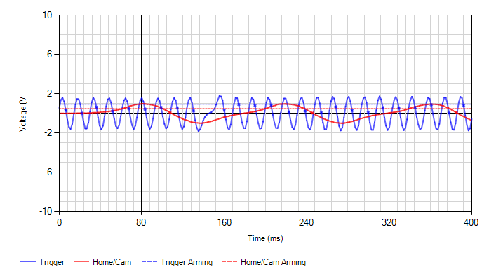
MTune built-in tool for trigger diagnostics.
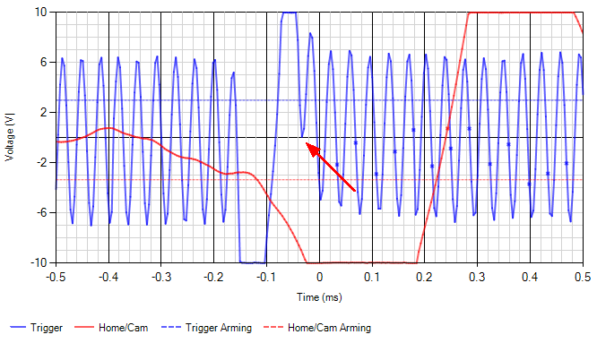
In the above image we can clearly see a missing tooth trigger wheel pattern (blue line), and a HOME/CAM sensor signal (red line).
The "dots" in the image is the approx position where MaxxECU triggers (the actual trigger point is the zero crossing, or ~1.1V for digital triggers).
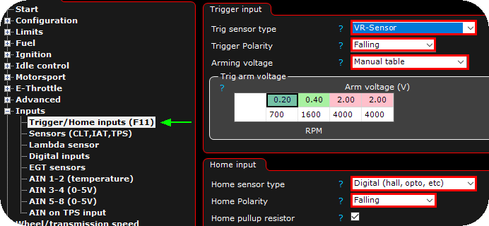
Trigger polarity explained
MaxxECU must know if you want to trigger on the "signal way up" or the "signal way down", this is also called rising and falling trigger.
A general rule is that we want to trigger on the "shortest and most distinct signal direction".
Note: Sometimes (especially on digital signals) the position of the HOME/CAM can be "adjusted" by changing the trigger polarity, if for some reason the HOME/CAM signal is to close for ex the "missing tooths". <-- Ensure that HOME/CAM position is distinc far from any missing teeths.
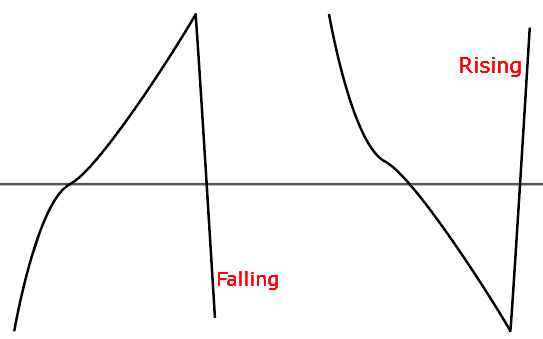
An illustration of the difference between rising and falling curves.
Trigger arm voltages and how to determine
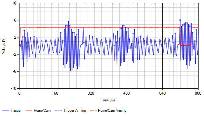
Since MTune 1.99, the trigger oscilloscope have additional information because of the new automatic tracking arming voltage feature.
Note:Trigger arm settings is only available when using a VR-sensor, and the recommended way is to set up the arming voltage in a manual way.
A good recommendation is to use 50% of the highest voltage as the trigger arm at current engine RPM.
The automatic trigger arm tracking feature. The blue and red "dotted" lines represents the actual voltages where MaxxECU triggers.
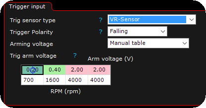
When using manual table, you tell MaxxECU on which trigger voltage to actually arm it as a signal from the sensor.

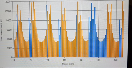
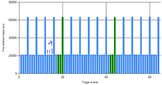
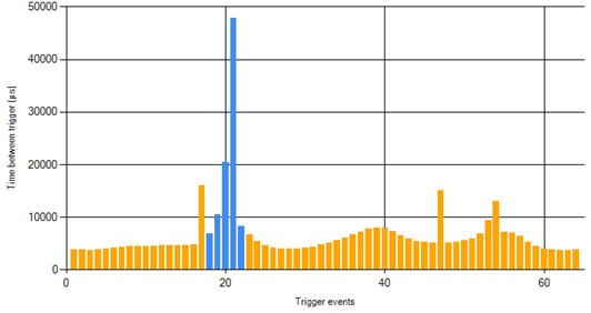
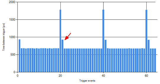
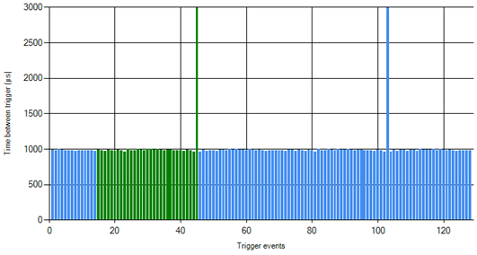
Trigger logger (Diagnostics --> Trigger logger)
This built-in feature is using the trigger settings to reflect the trigger pattern which is used by MaxxECU.
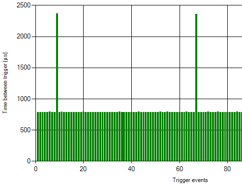
Each bin represent the time between each trigger input to the system, in the above example, a 60-2 trigger wheel is used, therefore there should be 58 "equal" height of bins before there is a three times higher bin, which represents the "missing tooth" space.
Note: Green and Blue mean the ECU doesn't have any trigger problems (but there could still be problems it's not seeing). Orange indicates some problem.
Using the Live-logger when dealing with trigger issues or trying to get engine RPM
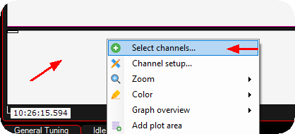
1. Right click on the live-logger area, click on Select channels.
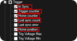
2. Check the above values, and confirm by pressing the OK button.
Note: RPM is also a good value to see...
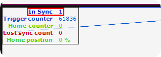
3. During cranking or an running engine, the In Sync value should always be "1".
Note: In sync = "0" means the trigger system is not synced, and will never fire either ignition or injectors.
Depending on which trigger system you are using, also check that Trigger counter increase during cranking, if you have a home/cam sensor, make sure the Home counter increasing during cranking.
Typical problems and solutions
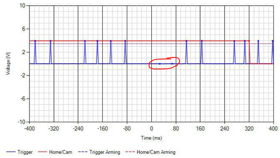
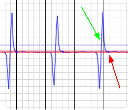
No zero voltage crossings
When a trigger signal (blue line) looks like the above, it will most likely generate a trigger error because the signal does not have a zero voltage crossings, it is most likely because the voltage from the sensors suddenly gets a spike, and MaxxECU protects itself and the result can be a "magnetized" sensor.
A solution (in most cases) to fix the above is to mount an external ~3K ohm resistor in series with the trigger output signal and the MaxxECU trigger input.
Built-in tools
•Trigger Oscilloscope. <-- Please read and understand this tool before continuing.
•Trigger logger. <-- Please read and understand this tool before continuing.