Vehicle cover list
Vehicle |
Engine code |
Year |
LSU sensor |
Note |
Cadillac Escalade |
6.2L (V8) |
2007 - 2014 |
External sensor needed (included) |
|
Chevrolet Avalanche |
5.3L, 6.0L (V8) |
200 7- 2013 |
External sensor needed (included) |
|
Chevrolet Corvette C6 |
6.0L, 6.2L, 7.0L (V8) |
2006 - 2013 |
External sensor needed (included) |
2006 Verified |
Chevrolet Camaro SS |
6.2L, 7.0L (V8) |
2010 - 2015 |
External sensor needed (included) |
|
Chevrolet Express |
4.8L, 5.3L, 6.0L (V8) |
2008 - 2015 |
External sensor needed (included) |
|
Chevrolet Equinox |
3.4L (V6) |
2007 - 2009 |
External sensor needed (included) |
|
Chevrolet Impala |
3.5L, 3.9L (V6) |
2007 - 2009 |
External sensor needed (included) |
|
Chevrolet Malibu |
3.5L, 3.9L (V6) |
2007 - 2009 |
External sensor needed (included) |
|
Chevrolet Monte Carlo |
3.5L (V6) |
2007 - 2008 |
External sensor needed (included) |
|
Chevrolet Silverado |
4.8L, 5.3L, 6.0L, 6.2 (V8) |
2007 - 2013 |
External sensor needed (included) |
|
Chevrolet SS |
6.2L (V8) |
2014 - 2016 |
External sensor needed (included) |
|
Chevrolet Suburban |
5.3L, 6.0L, 6.2L (V8) |
2007 - 2014 |
External sensor needed (included) |
|
Chevrolet Tahoe |
4.8L, 5.3L, 6.2L (V8) |
2007 - 2014 |
External sensor needed (included) |
|
GMC Savana |
4.8L, 5.3L, 6.0L (V8) |
2008 - 2015 |
External sensor needed (included) |
|
GMC Sierra |
4.8L, 5.3L, 6.0L, 6.2 (V8) |
2007 - 2013 |
External sensor needed (included) |
|
GMC Yukon & Denali |
4.8L, 5.3L, 6.0L, 6.2L (V8) |
2007 - 2014 |
External sensor needed (included) |
|
Holden Commodore & HSV |
6.0L, 6.2L (V8) |
2006 - 2017 |
External sensor needed (included) |
|
Hummer H2 |
6.2L (V8) |
2008 - 2009 |
External sensor needed (included) |
|
Pontiac G6 |
3.5L, 3.9L (V6) |
2007 - 2009 |
External sensor needed (included) |
|
Pontiac G8 |
6.0L, 6.2L (V8) |
2008 - 2010 |
External sensor needed (included) |
|
Pontiac Torrent |
3.4L (V6) |
2007 - 2009 |
External sensor needed (included) |
|
Saturn Aura |
3.5L (V6) |
2007 - 2009 |
External sensor needed (included) |
Note: Manual transmission only!
(we are searching for an Swedish Corvette C6 Auto gearbox customer to do the implementation, please contact if you have one we can do some testings on).
Control options
Options |
OEM ECU PIN |
MaxxECU IO |
MaxxECU PRO |
Note |
8 injection sequential |
- |
INJ 1-8 |
YES |
|
8 ignition sequential |
- |
IGN 1-8 |
YES |
|
E-Throttle |
B5/B6 |
GPO 11, GPO 12 |
Yes |
|
Camshaft solenoid |
B16 |
GPO 30 |
Yes |
Only on some models (Camaro SS (L99 with automatic gearbox) |
Evap canister purge solenoid |
B8 |
GPO 29 |
Yes |
|
Evap canister vent solenoid |
A61 |
GPO 24 |
Yes |
|
Fuel pump primary |
A50 |
GPO 15 (+12V) |
YES |
|
Fuel pump secondary |
A51 |
GPO 16 (+12V) |
YES |
|
Tachometer |
A48 |
GPO 8 |
YES |
|
AC magnetic clutch |
A63 |
GPO 25 |
Yes |
|
AC pressure signal |
A12 |
AIN 9 |
YES |
|
Starter relay coil supply |
A4 |
DIN 5 |
YES |
|
Low FAN |
A58 |
GPO 2 |
YES |
|
High FAN |
A17 |
GPO 1 |
YES |
|
Knock sensors (OEM) |
B26, B29 |
KNOCK1, KNOCK2 |
YES |
|
Vehicle speed (individual wheel speed) |
|
YES |
|
|
Narrow band oxygen sensors |
- |
- |
Uses external (and included) Bosch LSU 4.2 wide band sensors |
|
MAF (OEM) |
A41 |
AIN 17 |
Yes |
MAF should be removed. Use stock MAP sensor or use the MaxxECU built-in. |
Service light/check engine light |
A68 |
GPO 26 |
Yes |
|
Instrument cluster/ABS |
|
Yes |
|
|
Traction button |
|
Yes |
|
|
Fuel consumption |
|
|
||
Fuel level primary input |
A16 |
AIN 1 |
YES |
|
Fuel level secondary input |
A70 |
AIN 2 |
YES |
|
Brake switch signal |
A9 |
DIN 1 |
YES |
|
ECT/CLT |
B21 |
CLT |
YES |
|
Oil level switch |
B33 |
DIN 2 |
YES |
Only on early models |
Oil pressure sensor |
B50 |
AIN 11 |
YES |
|
Generator turn on signal |
B61 |
IGN 9 |
YES |
|
Clutch position |
A26 |
AIN 18 |
Yes* |
Only available in REV2+ plugin adapters! |
IAT (in OEM MAF) |
A37 |
IAT |
YES |
Also paralell connected with extra 2-pin GT150 connector (6) |
Fuel tank pressure |
A24 |
AIN10 |
YES |
Not used for anything, but wired |
Starter enable relay control |
A52 |
GPO 5 |
YES |
|
Starter enable relay control |
A67 |
INJ 13 |
YES |
|
VSS output to ABS system |
A57 |
GPO 7 |
YES |
|
VSS high signal |
A71 |
IGN 12 |
Yes |
Experimental output |
VSS low signal |
A72 |
IGN 10 |
Yes |
Experimental output |
Generator field duty signal |
B32 |
- |
Not needed |
|
MAP sensor (OEM) |
B58 |
AIN 12 |
Yes |
Used as MAP sensor input in default NA basetune, for forced induction, please use the built-in MAP sensor in MaxxECU |
DME relay |
A59 |
GPO 23 |
Yes |
|
Bluetooth (MDash) |
|
|
Yes |
|
EGT option |
|
|
Yes, 8 Directly |
|
Cyl 6/7/10 shutoff valves |
B9, B14, B10 |
INJ 14/16/15 |
Yes* |
Only available in REV3 plugin adapters! |
Cyl 4 shutoff / Reverse gear lockout solenoid |
B11 |
INJ 12 |
Yes* |
Only available in REV3 plugin adapters! |
Fuel economy meter in dash |
Yes |
Needs to be manually calibrated, uses MaxxECU fuel consumption caluclation for output |
Plugin adapter description
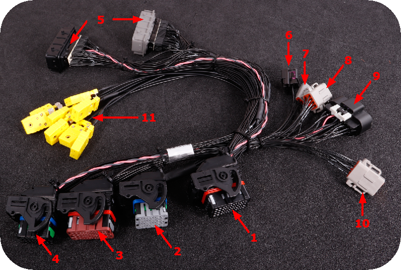
1 |
MaxxECU CMC connector 1 |
2 |
MaxxECU CMC connector 2 |
3 |
MaxxECU CMC connector 3 |
4 |
MaxxECU CMC connector 4 |
5 |
Vehicle harness connectors |
6 |
2-pin extra connector for external IAT |
7 |
3-pin connector (Flex fuel sensor) |
8 |
WBO 1 |
9 |
16-pin extra connector |
10 |
WBO 2 |
11 |
EGT harness (EGT1-8) |
ECU location and installation
Stock ECU is located behind right fender.
1.Disconnect battery from vehicle.
2.Remove right fender.
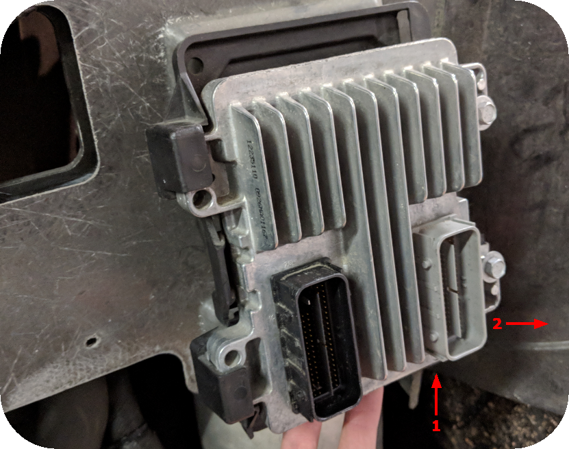
3.Remove and disconnect stock ECU from vehicle harness.
4.Remove old ECU brackets.
5.Install and secure the MaxxECU PRO unit with included screws.
6.Install MaxxECU PRO adapter harness.
7.Route the included MaxxECU MAP sensor hose to the intake manifold and connect into the MaxxECU (for boosted applications)
8.Optionally install a intake air temperature sensor (IAT) which is recommended (especially on boosted applications) and connect to MaxxECU.
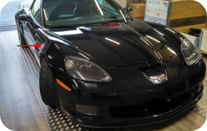
ECU location on the Corvette C6.
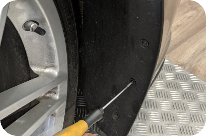
Remove the wheelhouse liner/mudguard, separated into two parts, remove them both.
Detach the fender from the front spoiler.
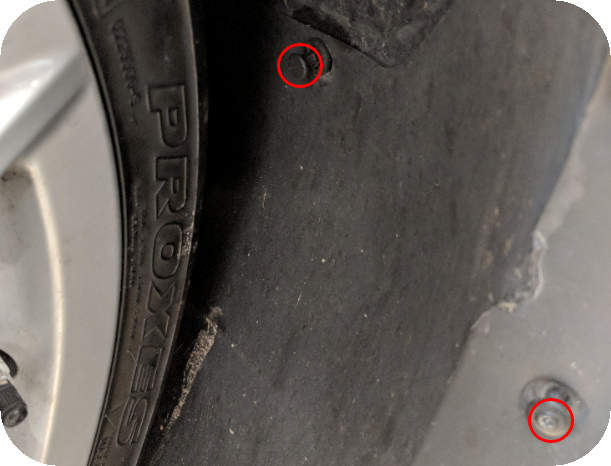
Remove the two most right screws that keeps the front spoiler in place in the front, so you are able to gently bend the front to access the hidden fender screw.
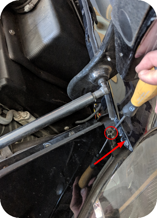
Gently move the front spoiler in the forward direction to access the hidden fender screw and remove it.
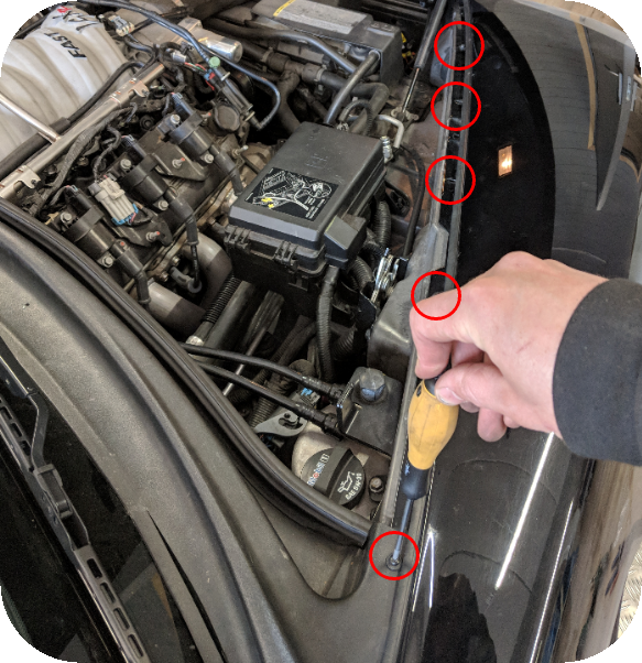
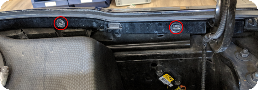
Remove all fender screws.
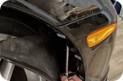
Somewhere here behind the stock ECU is another screw that holds the fender, please remove this one also.
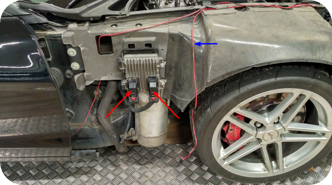
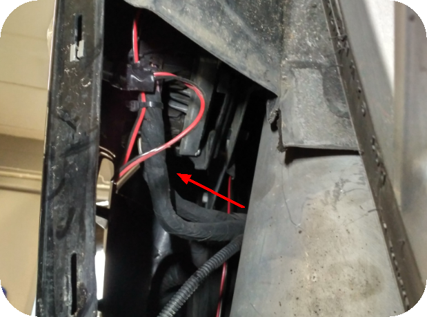
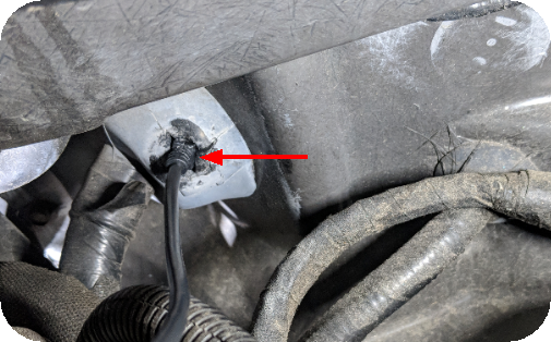
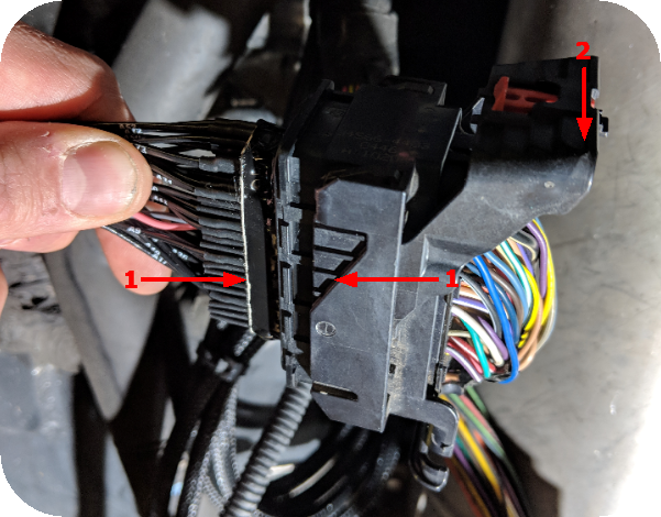
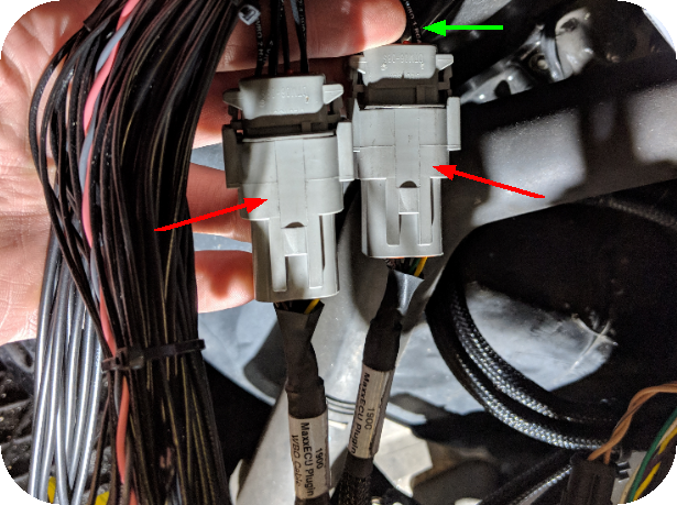
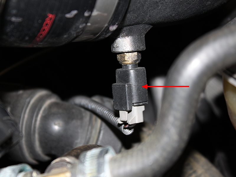
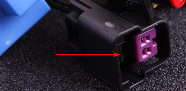
Remove the 2 ECU connectors (red arrows)
Note: Please do not pay attention to the red/black cable (blue arrow) in this picture, it is just a poor side indicator job...
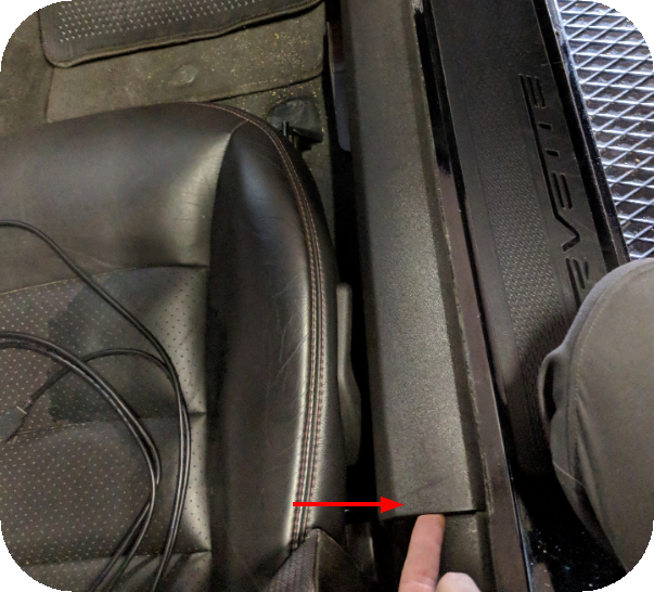
Open the passenger door, lift up the step-in protector and remove it.
Pull down the plastic protection under the passenger glove compartment.
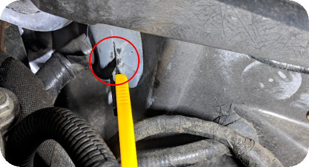
Use a sharp knife to cut a hole in the cable entry which is located on the other side of the firewall of the glove compartment, in the engine bay.
Route the included USB cable thru, you might need to use a screwdriver or other thicker object to help push the cable through.
The USB cable routed through the firewall, place the cable under the glove compartment for future usage.
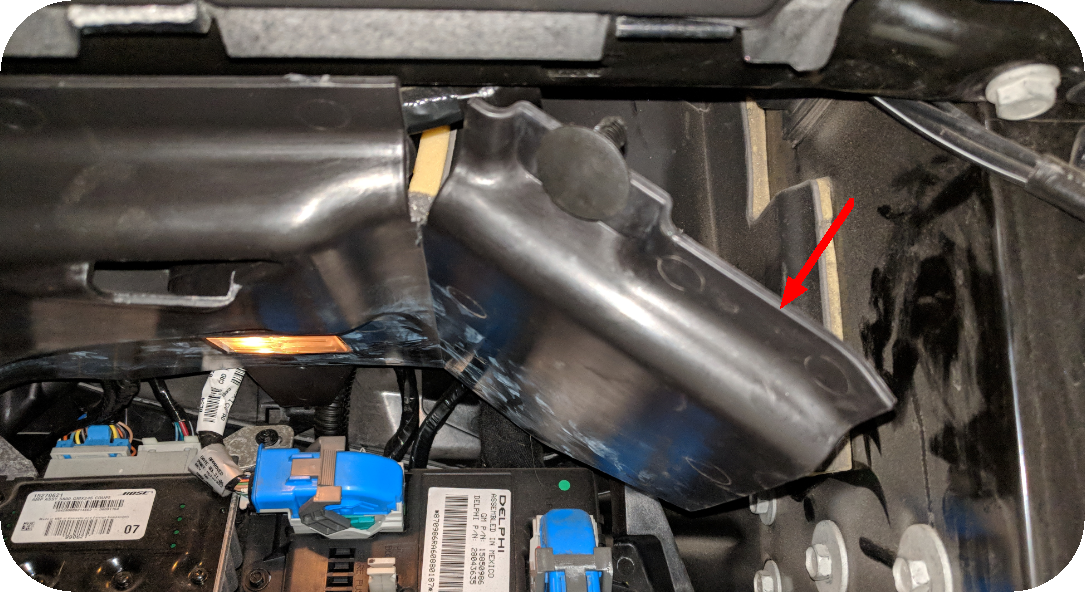
Lift up the stock ECU and push it outwards to remove it.
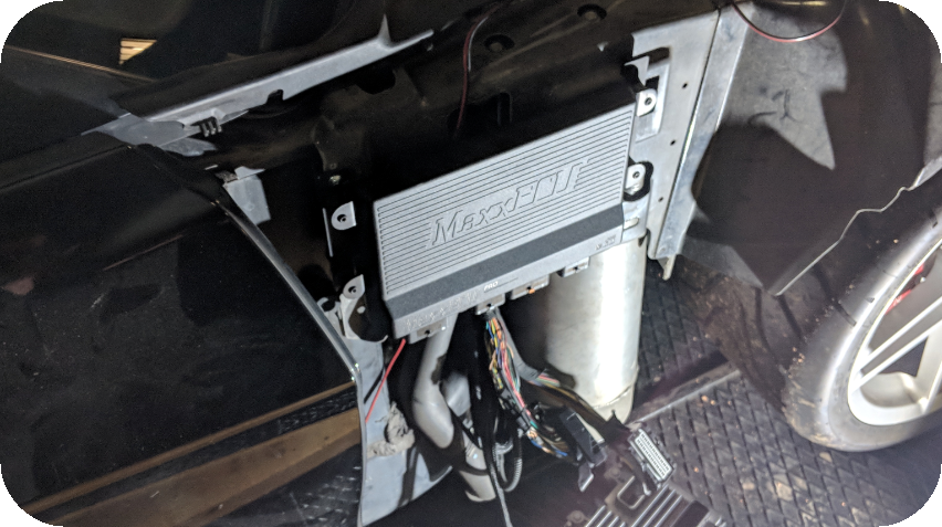
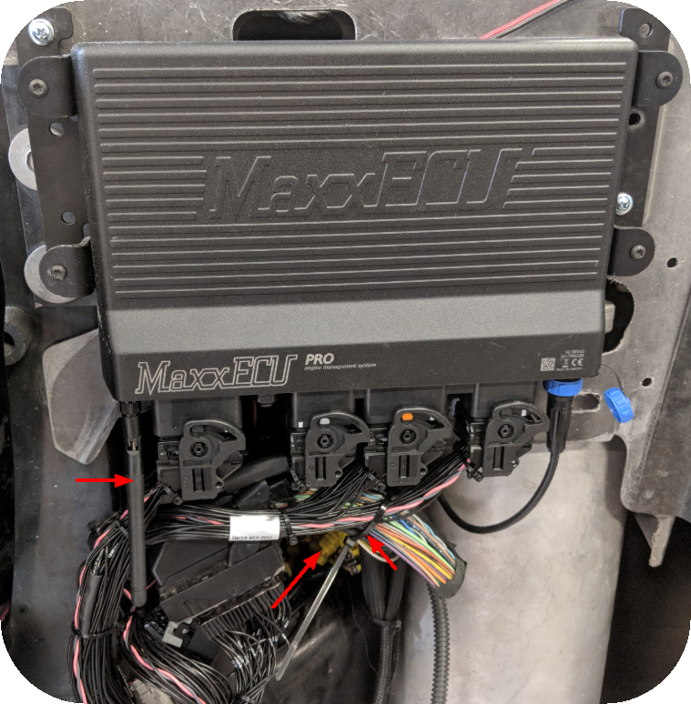
Mount the MaxxECU PRO unit with the included screws, be careful about the mounting position, see next step.
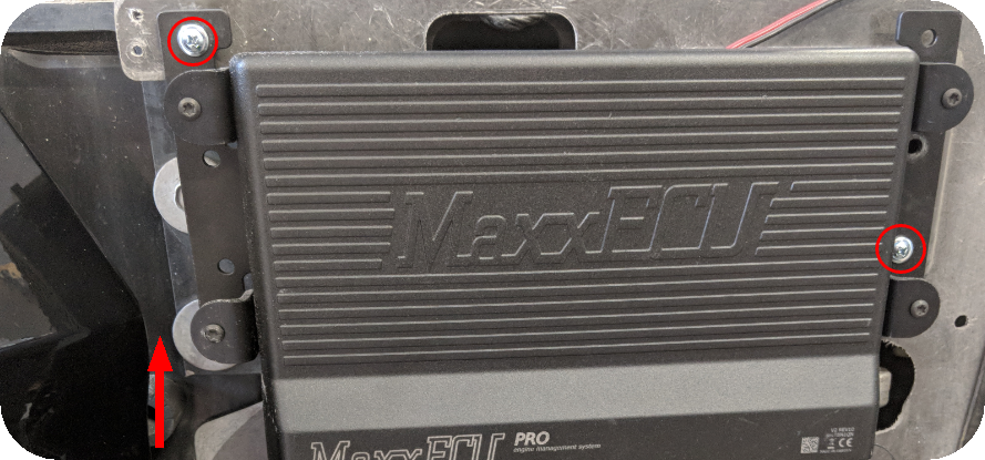
Example of MaxxECU PRO mounting position on the Corvette C6, be sure to have enough room between the MaxxECU PRO brackets and the door (red arrow), try to open the door fully before securing the MaxxECU PRO unit for good.
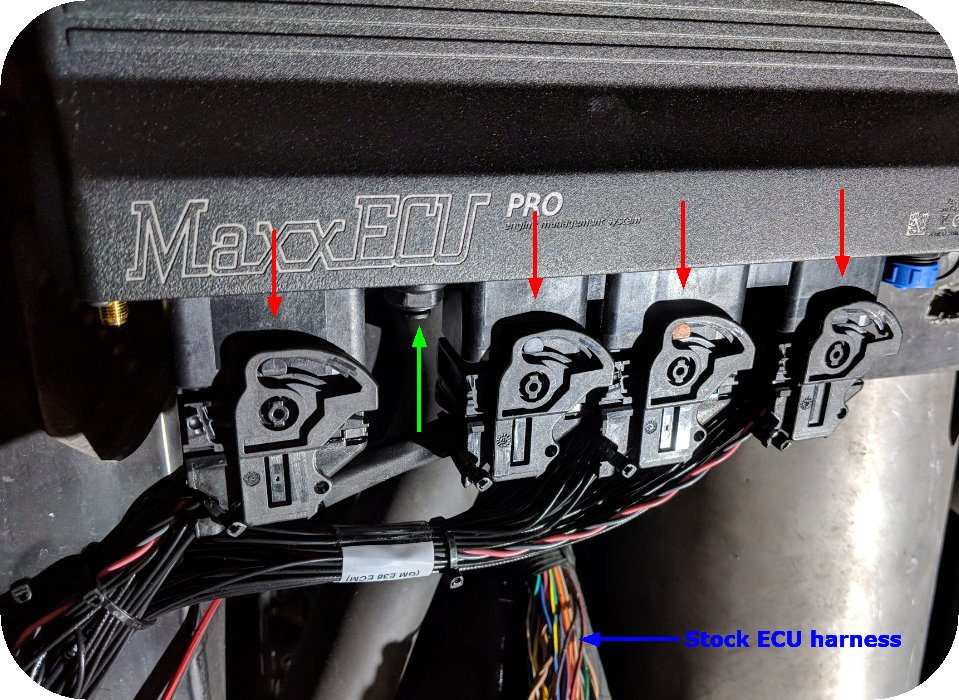
Install the MaxxECU adapter harness into the MaxxECU PRO unit by clicking in all CMC connectors.
Note: for boosted applications, please mount the included MAP sensor hose into the pneumatic connector (green arrow) in the MaxxECU and put the other end into the intake manifold. (The Plugin solution uses the stock MAP sensor mounted right after the E-Throttle body, but that sensor does not work with boosted applications). Do not forget to disable the external MAP sensor in the configuration for MaxxECU to understand to use the built-in MAP sensor instead in this case.
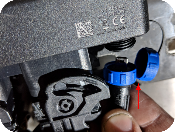
Mount and secure the included USB cable in the MaxxECU PRO unit.
Connect vehicle harness connectors with MaxxECU adapter harness.
Route the included Bosch LSU 4.2 sensors to each exhaust pipe, depending on your installation you might need to weld a new bung to make the sensors fit in the exhaust system.
Note: Make sure you route the LEFT side exhaust sensor to the WBO 1 connector, and the RIGHT side exhaust to WBO 2 connector, all cables are printed with their function.
Mount the included USB antenna.
Hide the extra EGT mini-K connector if they are not used.
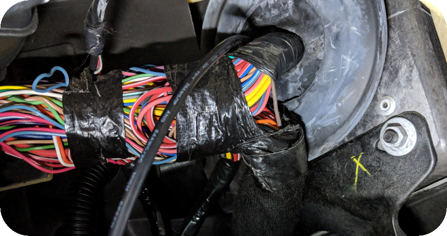
Use some wire straps to secure the stock vehicle harness from flying around.
Put back the wheel house mudguards, and reinstall the fender and frontspoiler. Secure all screws.
Connect battery.
Ignition on.
3-pin extra connector (Flex fuel sensor)
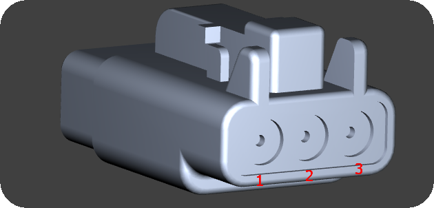
Seen from the wire side of the pre-wired connector.
Pin |
Description |
1 |
+12V power supply |
2 |
Sensor GND |
3 |
DIN 4 (sensor signal) |
8-pin extra connector (WBO 1. Cylinder 1,3,5,7 - LEFT)
Seen from the wire side of the pre-wired connector.
Pin |
Description |
1 |
Lambda VREF |
2 |
Lambda VS |
3 |
Lambda Shield (not always used) |
4 |
Lambda IP |
5 |
Lambda RCAL |
6 |
- |
7 |
Lambda +12V |
8 |
Lambda Heater- |
8-pin extra connector (WBO 2. Cylinder 2,4,6,8 - RIGHT)
Seen from the wire side of the pre-wired connector.
Pin |
Description |
1 |
Lambda VREF |
2 |
Lambda VS |
3 |
Lambda Shield (not always used) |
4 |
Lambda IP |
5 |
Lambda RCAL |
6 |
- |
7 |
Lambda +12V |
8 |
Lambda Heater- |
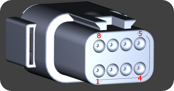
16-pin extra connector
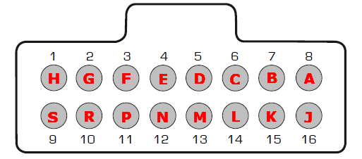
Note: Pinout is from the wire side of the pre-wired cable harness.
Pin |
Description |
Usage |
Note |
1 (H) |
AIN 3 |
|
|
2 (G) |
AIN 4 |
|
|
3 (F) |
+12V |
Output at ignition on |
|
4 (E) |
Engine GND |
- |
|
5 (D) |
CAN 2 H |
- |
|
6 (C) |
CAN 2 L |
- |
|
7 (B) |
GPO 7/DIN 3 |
|
|
8 (A) |
+5V sensor supply |
- |
|
9 (S) |
INJ 9 |
|
|
10 (R) |
INJ 10 |
|
|
11 (P) |
INJ 11 |
|
|
12 (N) |
Sensor GND |
- |
|
13 (M) |
AIN 13 (0-5V) |
|
|
14 (L) |
AIN 14 (0-5V) |
|
|
15 (K) |
AIN 15 (0-5V) |
|
|
16 (J) |
AIN 16 (0-5V) |
|
Optional: Install external intake air temperature (IAT) sensor
Some vehicles are not equipped with an intake air temperature (IAT) sensor and MaxxECU plugin solutions do have the
option to add a sensor.
The intake air temperature (IAT) sensor should be mounted to sense fresh air flow going into the engine.
Depending on the intake manifold construction, the position of the temperature sensor is not given, but preferably mount
the sensor in the intake, or in the pipe before/after the throttle.
IAT wiring
MaxxECU plugin solution are equipped with an optional 2-pin connector for optional IAT wiring.
Mating connector and wires for external IAT sensor.
Note: This plugin solution do take use if the stock IAT in the MAF, but usually the MAF is removed and the extra 2-pin GT150 connector is parallel wired with the MAF IAT.
See also
Example wirings of extra input and output