Samples times of AIN channels
AIN 1-4 are sampled at 1kHz.
AIN 5-12 are sampled at 100Hz.
The rest at about 50Hz.
Analog input (0-5V)
Description
User-defined name for this input to easily identify what's connected.
use as
Specifies whether to use this input as a analog 0-5V sensor input, or a digital input to trigger digital input functions.
•Analog 0-5v input - The input is used as a 0-5V analog sensor.
•Digital input - The input is used to trigger digital input functions.

Analog input
Class Specifies the sensor class type wired on the input, to be to used in the system. •User-defined input - Mostly used with pressure sensors or other 0-5V inputs not defined below. •ac pressure sensor - Can be calibrated in any unit. Required sensor for the AC MAGNETIC CLUTCH output function. •accelerometer, X. •accelerometer, Y. •accelerometer, Z. •CAN System EKPM control (0-100%) - Used to control the duty of the BMW EKP. •CAN system EXHAUST valve - Used on some OEM CAN system to control the exhaust valve(s). •CAN System Fuel Consumption Meter - Used on some OEM CAN system output data to a consumption meter (like displaying boost pressure instead). •CAN system power steering control - Used to control connected power steering modules. •CAN System Torque Value- Used on some OEM CAN system. •CAN SYSTEM USER output 1 - Used in some cases to control certain features in OEM CAN protocols. •fuel level 1 - Must be calibrated in the 0-100 % range. Used on some OEM CAN system to display fuel level in instrument cluster. •fuel level 2 - Must be calibrated in the 0-100 % range. Used on some OEM CAN system to display fuel level in instrument cluster. •fuel TEMP - Must be calibrated in deg C. •Crank case pressure - Must be calibrated in the pressure unit kPa. •Coolant temperature sensor - Must be calibrated in deg C. Overrides the CLT input wire and uses this input as CLT instead. •Coolant Pressure - Must be calibrated in the pressure unit kPa. •Differential temperature - Differential temp sensor. •E-throttle 1, position MAIN - Input from E-Throttle 1 position input 1 (main). •E-throttle 1, position BACKUP - Input from E-Throttle 1 position input 2 (backup). •E-throttle 2, position MAIN - Input from E-Throttle 2 position input 1 (main). <-- Only used if using dual E-Throttle bodies. •E-throttle 2, position BACKUP - Input from E-Throttle 2 position input 2 (backup). <-- Only used if using dual E-Throttle bodies. •E-throttle 1, pedal position MAIN - Input from E-pedal position input 1(main). •E-throttle 1, PEDAL position backup - Input from E-pedal position input 2 (backup). •EGT sensor 1 - 8 - Must be calibrated in deg C. •wastegate position 1 sensor - Must be calibrated in the 0-100 % range. •wastegate position 2 sensor - Must be calibrated in the 0-100 % range. •Exhaust backpressure - a pressure sensor mounted before the actual turbo, measureing exhaust pressures in the manifold. Must be calibrated in the pressure unit kPa. •Exhaust backpressure post turbo - a pressure sensor mounted AFTER the turbo measuring pressure in the exhaust system. Must be calibrated in the pressure unit kPa. •Engine oil pressure - Must be calibrated in the pressure unit kPa. Used on some OEM CAN system to display custom oil pressure in instrument cluster. •Engine oil temperature - Must be calibrated in deg C. Used on some OEM CAN system to display custom oil temperature in instrument cluster, or just used as a regular temperature sensor. If you have wired an oil temperature sensor to this input, select this. •engine compartment temperature sensor - Must be calibrated in deg C. Mostly used on Porsche vehicles, when there is a engine compartment temperature sensor mounted. •Ethanol % sensor (analog) - Must be calibrated in the 0-100 % range. Used with external ethanol sensor with an 0-5V output. (Do not use with the GM/Continental digital sensor). •External BARO sensor - Must be calibrated in the pressure unit kPa. When activated, MaxxECU uses this as BARO sensor instead of sampling the MAP sensor during power on. •External map sensor - Must be calibrated in the pressure unit kPa. When activated, MaxxECU internal MAP sensor is used as BARO sensor instead and the wired external MAP sensor is used as MAP instead. •External map sensor CAM reference - Must be calibrated in the pressure unit kPa. When enabled this sensor is used for the trigger system and the normal MAP-sensor is used for engine control. Useful for ITB bike engines with a manifold/bridge mounted MAP-sensor for engine control and a runner placed sensor for engine sync. •External wastegate pressure sensor - Must be calibrated in the pressure unit kPa. For usage with CO2 boost control. •Fuel pressure sensor 1 - Must be calibrated in the pressure unit kPa. •Fuel pressure sensor 2 - Must be calibrated in the pressure unit kPa. •Gear position sensor - 0-5V sensor to indicate the actual gear position on sequential gearboxes. •intake temperature sensor - Must be calibrated in deg C. Overrides the IAT input wire and uses this input as IAT instead. •lambda sensor bank A - Used when an external wideband sensor electronics is wired to an analog input, selection of lambda controller is done in Inputs --> Lambda sensor. •Lambda sensor bank B - Used when an external wideband sensor electronics is wired to an analog input, selection of lambda controller is done in Inputs --> Lambda sensor. •RPM, engine (not for fuel/ignition control). •Multi position switch 1. •Multi position switch 2. •Throttle position sensor - Must be calibrated in the 0-100 % range. •Transmission temperature - Must be calibrated in deg C. Transmission temp sensor. •Pattern generator RPM. •SHIFT FORCE SENSOR - Used by the Shiftcut system. •switch decoder 1 - Switch decoder. •switch decoder 2 - Switch decoder. •Tune selector - Can be used as any X or Y axis, or even as the 4D axle in any table to select different "tunes" in the whole system.
Note: Make sure to calibrate the sensor in the correct unit used by the system, especially if the sensors is used to control something, like fuel pressure, boost pressure, ac pressure etc.
Sensor Specifies the sensor calibration on the actual input channel. Select a predefined sensor from the list, or select the User-defined sensor option to create your own calibration table.
Unit Specifies the unit of the sensor used, ex bar, psi, % etc (you can create your own units here if needed...) Note: Only visible when the below Sensor calibration table is set to General purpose/no value conversion.
input settings
Filter The amount of filtering to be added to the input. Higher number = more filter --> Smoother signal.
Sensor supply tracking Corrects the sensor output in relation to the actual supply voltage. <-- Select correct +5V source. When battery voltage drops, the internal voltage regulators will also drop and in severe cases as the internal 5V regulators regulates, the calibration is adjusted to make sure a correct sensor output.
resolution Specifies the sensor resolution on the selected input. •1 (-32768 to +32767) - Values between -32768 and + 32767 can be used on the table (no decimals). •0.1 (-3276.8 to +3276.7) - Values between -3276.8 and + 3276.7 can be used on the table (one decimal). •0.01 (-327.68 to +327.67) - Values between -327.68 and + 327.67 can be used on the table (two decimals). •0.001 (-32.768 to +32.767) - Values between -32.768 and + 32.767 can be used on the table (three decimals). Note: When changing the resolution, any table value will be rescaled and changed accordingly and table min/max values will be used as stated above.
offset adjustment Some sensors require a voltage offset. This may be due to atmospheric changes or unforeseen external changes.
Error detection
error detection Whether to use error detection on the selection analog input channel or not. Default Disabled. •disabled - No error detection. •fail-safe value - Outputs a specified value when the system detects a failed sensor, based on user defined below/above thresholds. •set error code - Set an error code for the selected analog input channel. •fail-safe + set error code - Outputs a specified value when the system detects a failed sensor, based on user defined below/above thresholds and sets an error code.
Error below voltage Specifies the minimum voltage threshold before trigger error detection (any voltage below this value, will trigger the error detection).
Error above voltage Specifies the maximum voltage threshold before trigger error detection (any voltage above this value, will trigger the error detection).
Fail safe output value Specifies the sensor output value to be used when an error has been detected on the input voltage, according to the min (below) and max(above) settings.
Sensor calibration table
Note: A general rule with MaxxECU is to calibrate all sensors using metric units, then it could be displayed localized, ex calibrate in kPa and then the MTune system of measurement can be changed to US customary units to show ex PSI, for example and information, see MTune --> Configuration --> MTune settings.
Value type •General purpose/no value conversion. •Absolute pressure, enter kpa, display localized (kPa or PSI). <-- "absolute pressure" which includes the atmospheric pressure. •relative pressure, enter kpa, display localized (kPa or PSI). <-- "gauge pressure" and will not pay attention at atmospheric pressure.
Examples
Example - A predefined sensor exist in the list of sensors, but the sensor is in kPa and you want it to be displayed in BAR.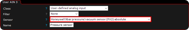 1. Select the sensor from the list
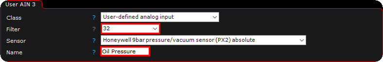 2. Add some filter to the sensor to get a smoother reading, and give the sensor a good name.
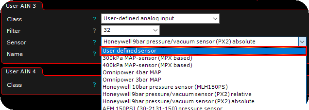 3. Select the User defined sensor from the dropdown list. Note: When selecting the User defined sensor from the list, MTune copies the values from the last selected (and current) sensor calibration data and make it visible in the Sensor calibration table to be edited.
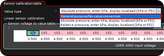 4. The sensor calibration is now visible, change the value type to General purpose/no value conversion.
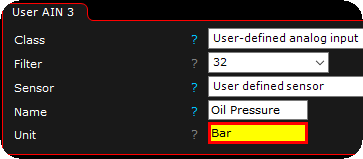 5. After changed the above value type to General purpose/no value conversion, the unit is now visible, change it to suit your need (in this example Bar).
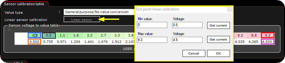 6. Change the calibration table to suit your sensor data. Blue box: Unit value to show at minimum voltage (0bar) from sensor (orange box, 0.5V in the above example). Red box: Unit value to show at maximum voltage (9.3bar) from the sensor (pink box, 4.5V in the above example).
Also, in the above example we used the "linear sensor" calibration button (yellow arrow) which will populate the calibration table with the settings you enter in the pop up box seen above.
 7. Verify the calibration and the output.
|
Digital input settings
Note: Voltage threshold on AIN (0-5V) input is 3.00V when used as digital input.
Active level Specifies whether function is active when voltage goes from high to low (falling edge) or low to high (rising edge).
Function Specifies the digital input function to trigger when the input gets active.
Function 2 Specifies the digital input function to trigger as function 2 when using the below latch function.
latch Adds a latching feature of the digital input, with possibility to trigger a secondary digital function. •None (active while the input is active) •Push: on, Push: off •Push: on, long Push: off •Push: on, long Push: function 2 on, push: both off
|