Note: if you only need to trigger one digital input from an analog input, see Digital inputs.
The Switch Decoder allows up to 4 switches/buttons to be connected to one analog input (0-5V or temp). Useful when you need more digital inputs and are out of pins, or when wiring 4 steering wheel buttons through a single wire (stock horn wire for example).
The ECU calculates the combination of active switches/buttons from the input voltage (analog input function Switch decoder).
Any number of switches can be active at the same time.
When using 0-5V inputs (with no internal pullup resistors) an external pullup resistor needs to be used. Ideally, 2500 is used (but values in the 1k to 5k range is OK).
When using TEMP inputs, no external pullup resistor is needed as the ECU has a 2490ohm internal pullup resistor.
Note: The PDM20, has 15000ohm pull-up to +12V as default, but can be software configured to use +5V pull-up.
Switch connections
- Resistors in series (most common)
2-4 resistors are connected in series between the analog input and ground. Each resistor has a switch wired across it that shorts it out when closed.
Recommended switched resistances:
Switch 1: Rpullup/2
Switch 2: Rpullup/4
Switch 3: Rpullup/8
Switch 4: Rpullup/16
The first switch resistor should be about half of the pullup resistor value, and each subsequent switch resistor is half of the previous resistor (some variations are acceptable).
With a 2500 (2490) ohm pullup resistor, use:
Switch 1: 1200ohm
Switch 2: 620ohm
Switch 3: 300ohm
Switch 4: 150ohm
SERIES example wiring
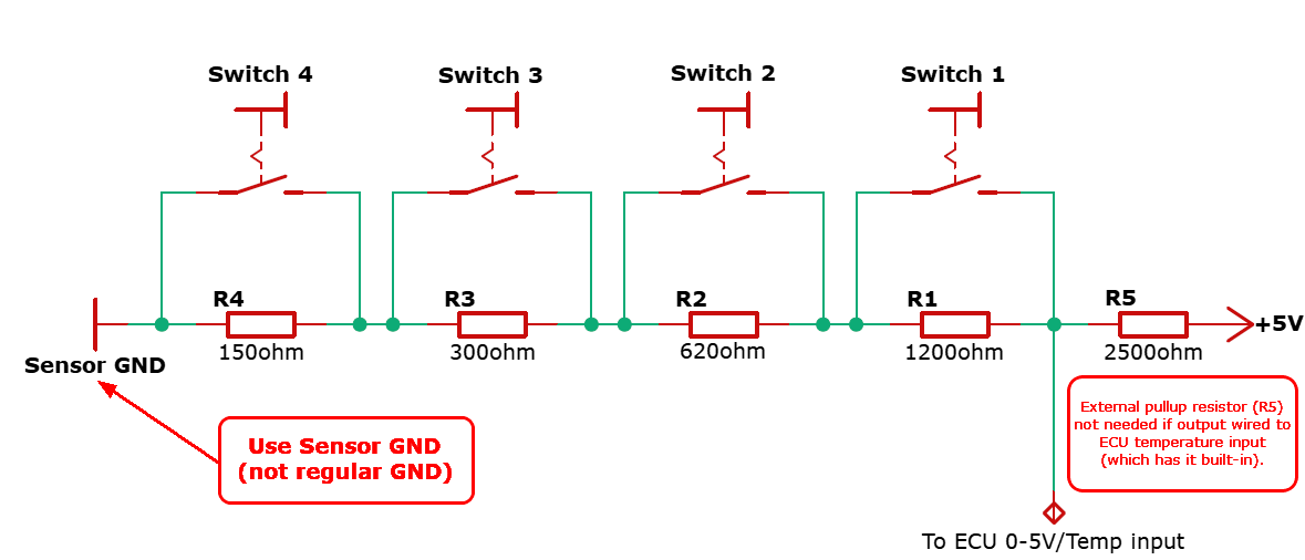
Example SERIES wiring using the analog input function Switch decoder.
- Resistors in parallel.
This wiring method is particularly useful when the switches already share a common ground, such as many OEM switch clusters or transmission shifters. It also allows all resistors to be placed together on a single PCB, requiring only one signal wire and one grounded wire to each switch.
Recommended switched resistances:
Switch 1: Rpullup*2
Switch 2: Rpullup*4
Switch 3: Rpullup*8
Switch 4: Rpullup*16
(For example, 4k7, 10k, 20k and 39k for a standard 2.5kohm internal pullup resistor)
Each switch has its own resistor connected to ground. Closing a switch connects that resistor between the analog input and ground, while all switches share a common ground connection.
Unlike the Series method, the resistor values increase for each switch position, causing the measured voltage to decrease in binary-weighted steps.
2-4 branches are connected in parallel between the analog input and ground.
Each branch consists of a resistor in series with a switch, so closing a switch connects that resistor to ground.
Notes
•Resistor values do not need to be exact, but they should follow the recommended binary-weighted ratio for reliable switch position detection.
•Both Series and Parallel wiring support 2–4 switches.
•Use Series for most new installations. Use Parallel when working with existing switch assemblies that have a common ground, or when it is more practical to place all resistors on a PCB.
Switch decoder
Used inputs
Specifies the number of input switches used, see above wiring example.
Switch connections
Selects how the resistors are connected in the switch network used by the Switch Decoder.
•series - Resistors in series with shorting switches.
•parallel - Switches connect resistors to ground.
settling delay
Used delay to prevent fault triggering, default is 0.05s. Increase if you experience double/fault triggers.
Resistors
Pullup resistor
Specifies the pullup resistor used (R5 in the above example).
Note: Enter 2490ohm if using TEMP inputs built-in pullup resistor.
Input X resistor
Specifies the resistor associated with the selected switch input. See above text and wiring example how to calculate since specific relationships NEEDS to be maintained.
Function
Function
Specifies the Digital input function to trigger when the corresponding active state for the selected input matches.
active state
Specifies whether the digital input function set should be triggered when the switch active state is closed or open.
latch
Adds a latching feature of the digital input.
•None (active while the input is active)
•Push: on, Push: off
•Push: on, long Push: off
The available RealTime Data values
Switch Multiplex 1 In 1, Switch 1 state (1 = closed)
Switch Multiplex 1 In 2, Switch 2 state (1 = closed)
Switch Multiplex 1 In 3, Switch 3 state (1 = closed)
Switch Multiplex 1 In 4, Switch 4 state (1 = closed)
Switch Multiplex 1 Voltage Error, the deviation from the current voltage and the closest theoretical state voltage. This should not be more than 20mV in any switch combination. If it's larger check your resistors and wiring. This can also be used to fine-tune the entered resistance values to minimize the error.
Note: DON NOT USE THIS FEATURE TO TRIGGER FUNCTIONS THAT IF THEY WERE TO GLITCH WOULD CAUSE DAMAGE (Transbrakes for example).
In case of bad connections in switches, wiring, or connections there's a small chance that this resistance would be decoded as an actual switch state and cause problems.
Example
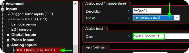
1. Configure the wired input class to Switch decoder (in our example we use the temperature input AIN 1 (which has a built-in pullup resistor)).
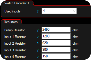
2. Set the wired switches (four in our example), and enter the resistor values used, see the above information and how to calculate.
Note: Enter 2490ohm if using TEMP inputs built-in pullup resistor.
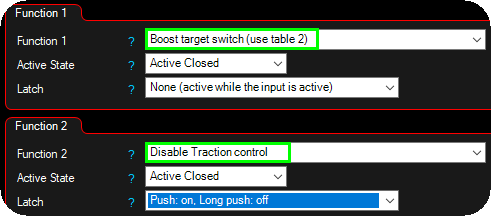
3. Set function, state and latch to suit your need, in our example we have set:
•When switch 1 is closed, we activate the secondary boost table.
•When switch 2 is pressed, we disable traction control features, and when the system detects a long press, we activate the traction control features again (it should be easy to deactivate limiting features, and hard to active them, right :))