Tachometer output
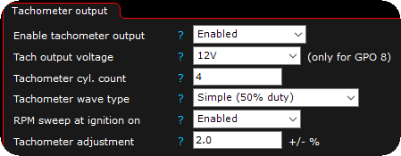
enable tachometer output
Enable or disables tachometer output on the selected output.
•DISabled - No output.
•ENABLED - Tachometer output is enabled.
•TEST MODE - Tachometer output is set to a test mode with a new test value available to test and calibrate the output to match engine RPM.
Tach output voltage
Note: Selectable pullup voltage can only be used on GPO 8.
•12V - Output uses a pull-up to +12V on the GPO 8 output.
•5V - Output uses a a pull-up to +5V on the GPO 8 output. <-- Try this one first if you are unsure of the tachometer voltage.
Tachometer cyl. count
Number of cylinders the tachometer is made for.
Tachometer wave type
•Simple (50% duty) - Most used option, select this if unsure of the wave type.
•user defined duty % - Uses the below tachometer output duty value.
•user defined dwell time - Uses the below tachometer output dwell value.
Tachometer output duty
User defined output duty to be used on the output.
Tachometer output dwell
User defined output dwell, specifies in milliseconds how long the output will be low.
RPM sweep at ignition on
Sweep the tachometer to RPM limit at ECU power on.
•DISabled - No sweep at power on.
•ENABLED - Sweeps the tachometer at ECU power ON.
•ENABLED with a 1.5 sec activation delay - The output sweep is shortly delayed (1.5 sec) for slower instrument clusters to be able to wake up before the sweep starts.
•ENABLED with a 3 sec activation delay - The output sweep is shortly delayed (3.0 sec) for slower instrument clusters to be able to wake up before the sweep starts.
•ENABLED with a 5 sec activation delay - The output sweep is shortly delayed (5.0 sec) for slower instrument clusters to be able to wake up before the sweep starts.
sweep RPM type
Selects whether to use the current rev limiter value, or a static RPM value.
•current rev-limiter - Uses the current rev limit value.
•set rpm - The used RPM sweep value to use.
sweep RPM type
User defined sweep rpm to use.
Tachometer calibration
calibration mode
Specifies whether to use a single value or a table for the calibration.
•single value - Single value calibration value.
•table - Calibration value from the table.
Tachometer adjustment
Adjustment for tachometer output. Use the test mode to adjust, see examples below.
Tachometer value presentation
value presentation 1
Function to show a value change on the tachometer output, from a RealTime Data value change or digital input Tachometer/speedometer, show monitor value x change.
•disabled
•enabled, by value change
•enabled, by digital input
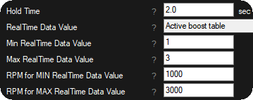
hold time
Specifies the amount of time in seconds to hold the output RPM.
RealTime data value
Specifies the RealTime Data value used as the source.
MIN RealTime data value
Specifies the MIN value of the selected RealTime data value, to be used as the output RPM minimum value below.
MAX RealTime data value
Specifies the MAX value of the selected RealTime data value, to be used as the output RPM maximum value below.
RPM for MIN RealTIME data value
Specifies the output RPM to show, when the selected RealTime data value is MIN RealTime data value.
RPM for max RealTIME data value
Specifies the output RPM to show, when the selected RealTime data value is MAX RealTime data value.
Examples


Example settings to reflect a change of the active boost table on the tachometer.

Example in the logger when changing active boost state.
Tachometer value presentation
OEM CAN protocols workable with the tachometer value presentation
•Audi A4 B7 VAG PL47 2006 (MED 9.1). Read note below!
•Audi RS6 C5 VAG PL45 (ME 7.1.1). Read note below!
•Audi S3 1.8T 2003 VAG PQ34 (ME 7.5). Read note below!
•Audi S3 8P 2010 (MED 9.1). Read note below!
•Audi S4 B6 VAG PL46 (ME 7.1.1). Read note below!
•Nissan Patrol TB48 Y61 (ME C23).
•Volvo ME 7.0.1 (250kbit). <-- Make sure to disable the "RPM sweep at ignition on".
Note: for all the above Audi CAN protocols, we disable the value presentation function if any DSG control is activated, to prevent TCU error. Also, be sure to disable the RPM sweep at ignition on function, otherwise you might get an oil pressure warning in dash.
Tachometer test
Output rpm
Available when the test mode is enabled, set to a value to be sent to the actual output without starting the engine. Use the above settings to adjust to match engine RPM with the tachometer output.
Examples

Example of a 4-cylinder tachometer wired to a GPO.

When the Enable tachometer output is set to Test mode this option is availabe, test RPM for easy calibration of tachometers.
Note: The combination of engine cylinders and tachometers used are unlimited, for ex. you can have a 4 cylinder engine and use a tachometer from a 8-cylinder or even a 5-cylinder tachometer, the tachometer output will work as expected.
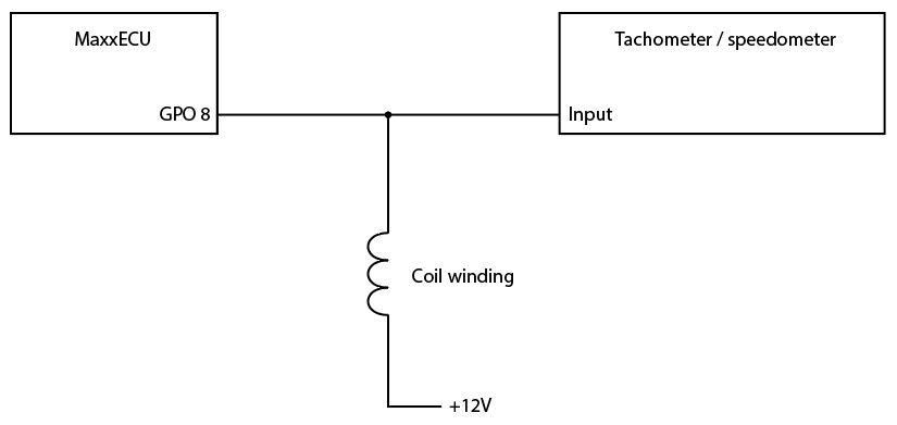
Use a coil winding to trigger "coil triggered tachometers"
Some tachometers are directly triggered from the stock coil, during the change to MaxxECU, you probably wire your tachometer to the MaxxECU GPO 8 and in some cases the Tach output does not work.

In the above example, we have taken apart a regular 30A relay and used the coil winding as a resistor to +12V. In this case the relay coil acts as the coil and gives the tacho the inductive kickback it wants.
Note: The GPO 8 output is designed to give a higher flyback voltage with inductive loads (like the relay coil).
Note: some older Volvo cars needs the GPO7 to be used on the tachometer signal because of the built-in +5V pullup.
