DCT UP shift
Shiftcut on UP shift is not "needed", it works flawlessly without any kind of cut, but might increase the ware of your clutches, but it shifts fine without....your decision.
Note: The shiftcut event is ALWAYS triggered from the DCT control to the shiftcut system during an up shift event, regardless of Drivelogic mode, engine load or pedal position, it is up to the Shiftcut settings to decide whether to do a shiftcut or not.
The above image is an example of how the different signals MaxxECU is received during an up shift event from a M3 TCU, and also how it should look like!
1. The shift signal is received (Green).
2. Gear indication (Blue) will increment during the up shift event.
3. The Torque reduction signal sends a signal to the MaxxECU indicating to lower engine torque (shiftcut) during the shift operation.
How to determine the Shiftcut source
Multiple torque reduction signals in one single shift operation
If you get the above, several torque reduction signals during one single up shift event, you cannot use torque request from tcu as the shiftcut source. You have to use shift signal from tcu as shiftcut source.
Lack of torque reduction signal randomly
In the above example, we get a very short, or not even an Torque reduction Request signal at all, in the above case, you must use shift signal from tcu as shiftcut source.
Note: it is always safest to use the Shift signal from TCU.
Example shiftcut delay time when using the shiftcut signal from TCU as shiftcut source.
Note: If using the Shift signal from TCU as shiftcut source, an shift cut delay of around 0.020(20ms) to 0.040sek(40ms) is necessary to make torque reduction at the correct time.
|
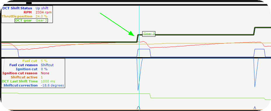
Example interesting data during an DCT up shift operation, with shiftcut feature activated.
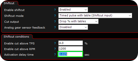
Example shiftcut setting, here different settings for up and down shifts using the True 4D feature of MaxxECU. See DCT shifting options for all shifting options.
The above image is an example of how the different signals MaxxECU is received during an up shift event from a M3 TCU, and also how it should look like!
1. The shift signal is received (Green).
2. Gear indication (Blue) will increment during the up shift event.
3. The Torque reduction signal sends a signal to the MaxxECU indicating to lower engine torque (shiftcut) during the shift operation.
How to determine the Shiftcut source
Multiple torque reduction signals in one single shift operation
If you get the above, several torque reduction signals during one single up shift event, you cannot use torque request from tcu as the shiftcut source. You have to use shift signal from tcu as shiftcut source.
Lack of torque reduction signal randomly
In the above example, we get a very short, or not even an Torque reduction Request signal at all, in the above case, you must use shift signal from tcu as shiftcut source.
Note: it is always safest to use the Shift signal from TCU.
Example shiftcut delay time when using the shiftcut signal from TCU as shiftcut source.
Note: If using the Shift signal from TCU as shiftcut source, an shift cut delay of around 0.020(20ms) to 0.040sek(40ms) is necessary to make torque reduction at the correct time.
|
How to DCT downshift (GEN1 drivelogic mode 1,2,3 / GEN2 drivelogic mode 1)
The TCU sends an downshift event to MaxxECU (via CAN) which internally activates the Throttle blip feature, which is a required to successfully downshift in this mode.
Downshift with pedal below 2%.
Just press the downshift, and it will downshift :)
Note: The shiftcut event is NOT triggered below 2% pedal in ANY drivelogic mode.
DCT downshift with pedal over 2%.
Over 2% pedal, the torque table is used, and in some cases it MIGHT need to use the shiftcut feature to reduce engine power during a downshift.
Note: The shiftcut event IS always triggered over 2% pedal position in ANY drivelogic mode.
Note: The shiftcut event is always triggered when there is an down shift event from the DCT, when pedal is over 2% position.
1. Do some basic Shiftcut setting.
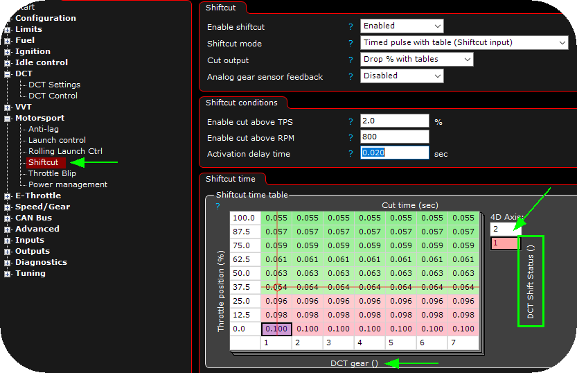
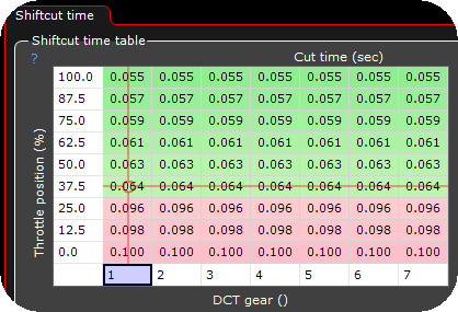
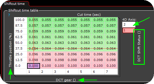
2. Change the axis of the Shiftcut time table to suit your need. These shiftcut time table will always be used, regardless of an up shift or an down shift event.
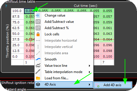
3. Right click anywhere on the table, select 4D Axis --> Add 4D axis. True 4D is explained here.
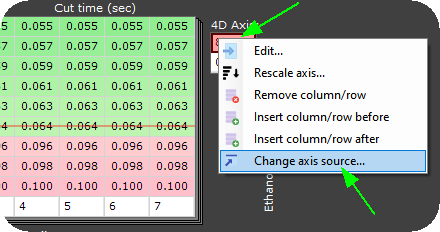
4. Right click on the 4D axis table, select Change axis source and change to the DCT Shifter Status available under DCT Trans.
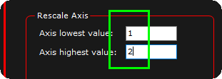
5. Rescale like the above.
Note: DCT Shift Status, 1 = SHIFT_UP, 2 = SHIFT_DOWN.
6. If you have done everything correctly, it will look something like this, which means up shift and down shift have different shiftcut time tables.
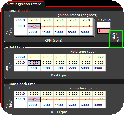
7. Add 4D axis on Retard angle to have a different ignition retard on up and down shift (if needed, that depends on your application). Change to suit your need.
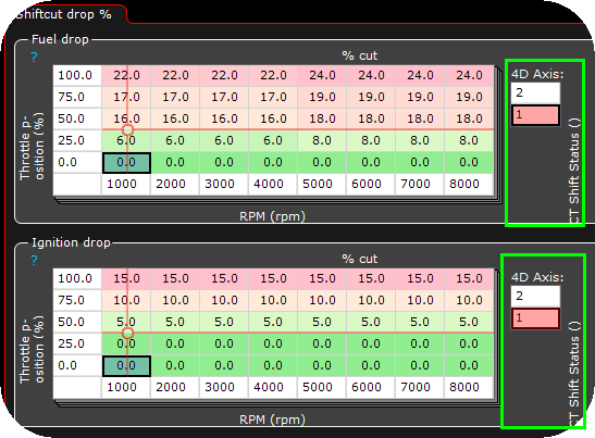
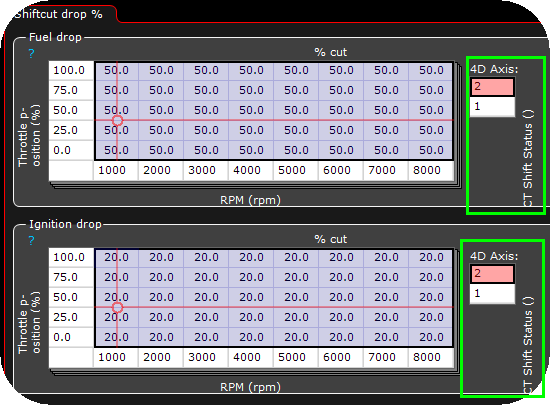
8. Add a 4D axis to the ignition and fuel drop tables, the above shows example of drop tables for an up shift.
9. Example drop tables on a down shift.
Note: We have seen that just a little power reduction during a downshift, will increase the shift speed, cause the TCU needs to "detect" some reduced power during this shift operation.
|
How to DCT downshift and throttle blip (GEN1 drivelogic mode 4,5,6 / SPORT MODE / GEN2 drivelogic 3)
Downshift with pedal below 2% (blip is required)
The TCU sends an downshift event to MaxxECU (via CAN) which internally activates the Throttle blip feature, which is a required to successfully downshift in this mode.
Note: The shiftcut event is NOT triggered below 2% pedal in ANY drivelogic mode.
Note: Before you are trying to setup blip, we assume a valid DCT torque table is tuned in DCT Control and that up shifting is working properly.
1. In DCT settings, blip delay, set a default blip delay of 60ms blip delay (as a starting point).
Note: Values below 40ms might make the system react strangely. Over 80ms it might throw out the gear and go into idle rpm.
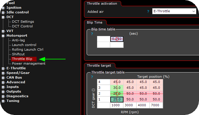
2. In Motorsport --> Throttle blip, set basic settings. The above might be a good starting point. Depending on engine size and response it requires different blip time and throttle targets, individually by gear and RPM.
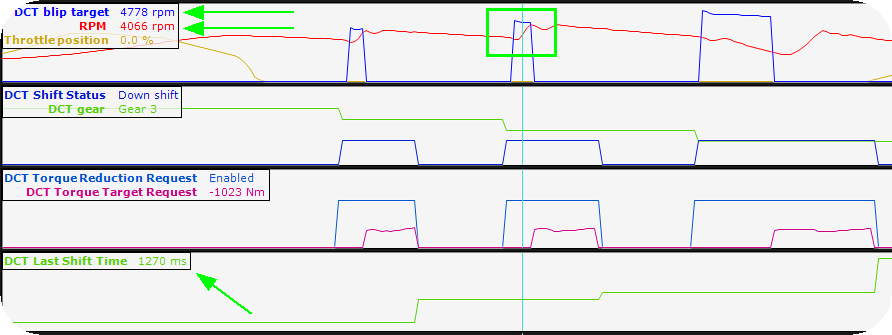
3. The TCU calculates a requested "Blip Target engine RPM" right before the blip event is triggered, this value can be seen in the logger (DCT Blip Target RPM). You need to make your blip settings so that the engine RPM gets right above this the blip target RPM, from our experience it is better to have a too high engine RPM than the actual target blip RPM to make sure the TCU wont disengage the clutches. Also pay attention to the DCT last shift time, when over 1500ms, it is most likely there is something wrong.
NOTE: DCT BLIP TARGET RPM is NOT available for the GEN2 protocol.
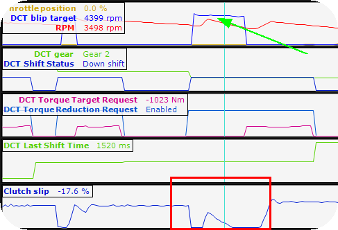
By watching the clutch slip (%) during a shift operation, which should look like the above, all is good.
Here we can see a clear example of that the TCU is unhappy with our blip settings, in the above example we did not achieve the wanted engine RPM, and therefore the TCU disengages the clutches and the shift operation took a very long time to be completed.
|
DCT downshift with pedal over 2%.
Over 2% pedal, the torque table is used, and in some cases it MIGHT need to use the shiftcut feature to reduce engine power during a downshift.
Note: The shiftcut event IS always triggered over 2% pedal position in ANY drivelogic mode.
Note: The shiftcut event is always triggered when there is an down shift event from the DCT, when pedal is over 2% position.
1. Do some basic Shiftcut setting.
2. Change the axis of the Shiftcut time table to suit your need. These shiftcut time table will always be used, regardless of an up shift or an down shift event.
3. Right click anywhere on the table, select 4D Axis --> Add 4D axis. True 4D is explained here.
4. Right click on the 4D axis table, select Change axis source and change to the DCT Shifter Status available under DCT Trans.
5. Rescale like the above.
Note: DCT Shift Status, 1 = SHIFT_UP, 2 = SHIFT_DOWN.
6. If you have done everything correctly, it will look something like this, which means up shift and down shift have different shiftcut time tables.
7. Add 4D axis on Retard angle to have a different ignition retard on up and down shift (if needed, that depends on your application). Change to suit your need.
8. Add a 4D axis to the ignition and fuel drop tables, the above shows example of drop tables for an up shift.
9. Example drop tables on a down shift.
Note: We have seen that just a little power reduction during a downshift, will increase the shift speed, cause the TCU needs to "detect" some reduced power during this shift operation.
|
How to DCT downshift and throttle blip (GEN2) new 2025 improved strategy
The TCU sends an downshift event to MaxxECU (via CAN) which internally activates the Throttle blip feature, which is a required to successfully downshift in this mode.
Uses a user-tunable PID loop to command throttle targets so engine speed tracks the blip-RPM setpoint in closed-loop, enabling quicker, more stable downshifts.
Prerequisite: the E-throttle must be accurately calibrated and responsive.
Use together with the 2025 shift strategy.
1. Ensure a proper engine torque table. Giving the system some extra throttle when on blip, might improve the downshift speed.
2. Create a user PID function in the Outputs -> Output config.
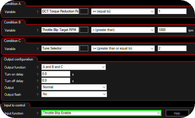
3. Create an internal output which triggers the throttle blip enable digital input, based on the above conditions. Advanced --> Internal outputs.
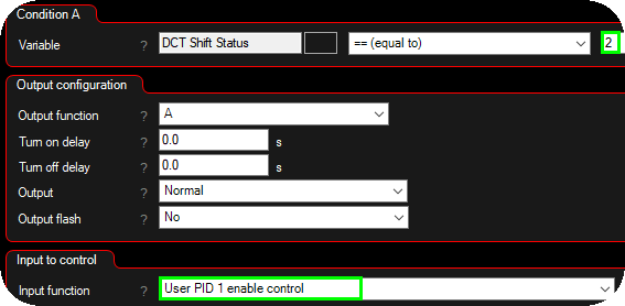
4. Create another internal output which enables the user pid 1 enable control feature when the DCT shift status is 2 (downshift).
5. Enable the throttle blip using the enable signal.
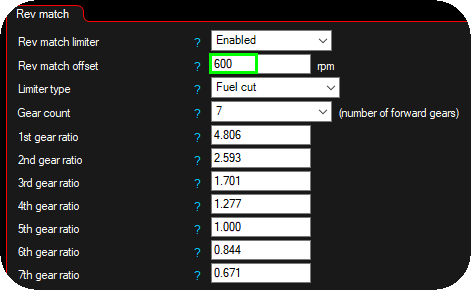
6. Optional rev match limiter with an rev match offset, to prevent too much overshoot as a protection.
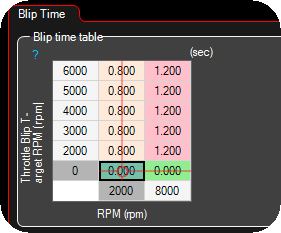
7. Max allowed blip times.
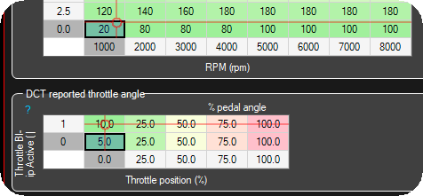
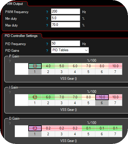
8. Set the throttle target to follow the user pid duty between 0 and 70%.
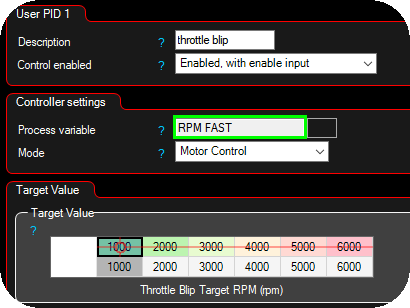
9. User PID 1 settings, use the RPM FAST as the process value and set a 1:1 target value conversion between the throttle blip target rpm and the output target rpm.
10. Setup basic User PID values., Most likely you need PID Gains using PID tables, example values to begin with.
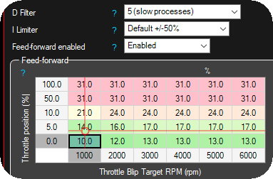
11. Set the Feed-Forward (FF) table first. It must predict the throttle command needed to reach the blip RPM setpoint so the PID only trims small residuals. If FF is off, the user-PID will react late/slow.
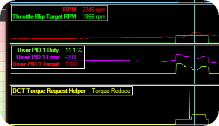
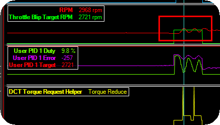
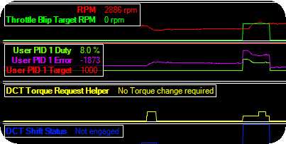
12. Adjust parameters to that the engine RPM is as close to the throttle blip target rpm as possible. Use the DCT Torque Request Helper for suggestions.
Small overshoot.
Oscillating engine RPM, PID parameters needs to be cooled down.
Slowly progressing to maintain a stable engine rpm during downshift, please watch the DCT shift status, it will be shorter and shorter when you are getting in the right direction.

