Terminated engine harness for GM LS engines.
Compatible with MaxxECU RACE only!
GM LS differences
Feature |
GEN III (5.7L LS1/LS6) |
GEN IV (6.0L LS2, 7.0L 6.2L LS3/LS4/LS7/LSX/LS9) |
Note |
Knock sensor |
1-wire, rear mounted |
On each side of the engine block, 2-wire |
|
CAM sensor position |
Rear |
In the front of engine. |
Wiring position change: A->C and C->A |
Alternator connector |
|
|
Superseal connector in the rear of engine, uses an cable adapter to fit the correct alternator. |
Crank sensor connector |
Position: Below right bank |
Position: Below right bank |
Superseal connector close to sensor, uses an cable adapter to fit the correct engine. |
Harness support
Terminated engine harness |
MaxxECU RACE I/O |
Note |
+12V to injectors, ignition |
Yes |
|
Cylinder head GND |
Engine GND |
|
OEM generator |
Yes |
|
OEM engine starter |
Yes |
*Can be an Eylet terminal on some engines |
Injectors |
INJ 1-8 |
Uses Bosch JPT connectors |
Ignition coils |
IGN 1-8 |
Stock coils used |
OEM coolant temperature sensor |
CLT |
Stock sensor used |
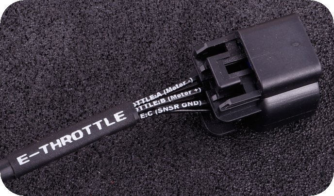
OEM E-Throttle position sensors |
TPS, AIN 3 |
Stock E-Throttle used |
IAT |
IAT |
External one needed (not included) |
OEM crank trigger |
TRIGGER |
Uses stock Trigger |
OEM HOME trigger |
HOME |
Uses stock Trigger |
OEM oil pressure sensor |
AIN 4 |
|
E-Throttle |
TPS AIN, AIN3, GPO 11, GPO 12 |
|
E-Pedal |
AIN5, AIN8 |
|
Boost solenoid |
GPO 1 |
2-way superseal connector (solenoid not included) |
OEM knock sensors |
KNOCK1, KNOCK2 |
Uses GEN IV OEM knock sensors |
MAP sensor hose in harness |
Yes |
To be mounted on intake |
Fuel pump relay control |
GPO 2/or use any available output |
|
Engine FAN relay control |
GPO 6/or use any available output |
|
Wideband LSU connector |
Yes |
Single LSU 4.2, secondary WBO CAN module can be used in the 4-pin connector in the rear. |
EGT option |
Yes, 8pcs direct |
|
Length
Start |
End |
Total length |
MaxxECU CMC connector |
Firewall entry/bushing |
800mm |
MaxxECU CMC connector |
LSU connector |
1850mm |
MaxxECU CMC connector |
IGN 1 coil connector |
2200mm |
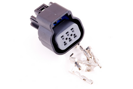
Harness connectors
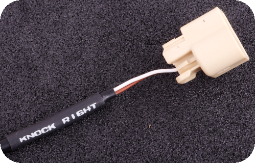
Knock sensor connectors (GEN IV).
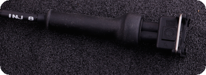
BOSCH JPT injector connectors.
Ignition coil connectors, for OEM coils.
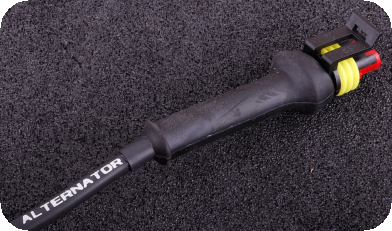
Since GEN III and GEN IV uses different alternators, the correct adapter cable must be used to the main harness.
•ID 1955 - Bosch alternator (2-pin connector)
•ID 1956 - Mitsubishi alternator (4-pin connector)
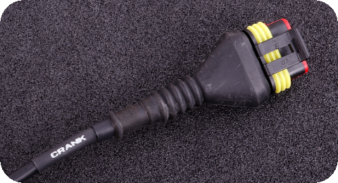
GEN III and GEN IV uses different connector/pinout on the CRANK TRIGGER, the correct adapter cable must be used to the main harness.
•ID 1957 - GEN III crank trigger adapter cable
•ID 1958 - GEN IV crank trigger adapter cable
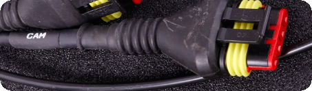
GEN III and GEN IV GM LS uses dfferent connector/pinout on the CAM, the correct adapter cable must be used to the main harness.
•ID 1959 - GEN III cam adapter cable
•ID 1960 - GEN IV cam adapter cable
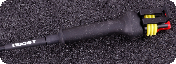
An extra cable with a 2-pin superseal connector is wired to be used with for ex a boost solenoid.
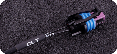
The OEM coolant temp (CLT) sensor connector.
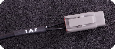
Intake Air Temperature (IAT) connector for the 1/8 IAT sensor.
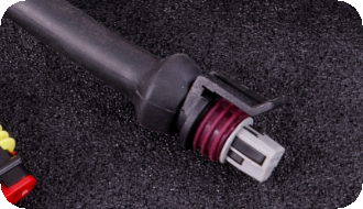
Oil pressure connector (honeywell) for the 3-pin OEM honeywell sensor.
4-pin connector (secondary WBO)
Pin |
Description |
Usage |
Note |
1 |
+12V |
+12 power supply |
|
2 |
CAN H |
|
|
3 |
CAN L |
|
|
4 |
Engine GND |
|
|
6-pin connector (E-pedal)
Pin |
Description |
Usage |
Note |
1 |
Sensor GND |
GND for all sensors, NEVER connect to engine GND |
|
2 |
Sensor GND |
GND for all sensors, NEVER connect to engine GND |
|
3 |
AIN 5 |
Used as Main Pedal position, marked wrongly on some harnesses! |
|
4 |
+5V sensor supply |
|
Power supply for all +5V sensors |
5 |
+5V sensor supply |
|
Power supply for all +5V sensors |
6 |
AIN 8 |
Used as Backup Pedal position |
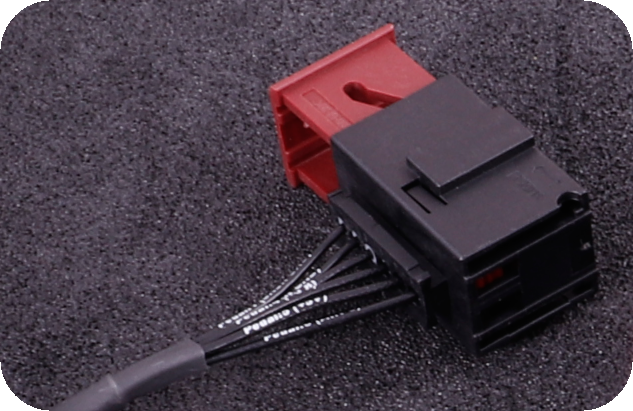
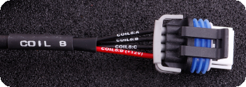
12-pin connector (seen from the wire side)
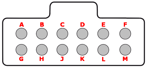
Note: Pinout is from the wiring side of the extra connector, not the terminated harness.
Pin |
Description |
Usage |
Note |
A |
+12V ignition coils power supply |
Connect to a +12V switched (and 20A fused) source |
|
B |
Engine ground |
Engine ground (if needed) |
|
C |
GPO 2 (fuel pump) |
GND output for relay control |
|
D |
GPO 6 (FAN) |
GND output for relay control |
|
E |
GPO 3 |
GND output for relay control |
|
F |
Engine starter (+12V) - Connect to ignition key or switch |
Put +12V on this wire from a switch or simply the ignition key crank pos. |
|
G |
+12V ECU power supply |
Connect to a +12V switched (and 15A fused) source |
|
H |
GPO 8/TACHO |
Selectable GND output with 5 or 12V pullup |
|
J |
GPO 15 (+12V) |
GND output for relay control |
|
K |
Motor 2 + (H-bridge output) |
* (if not using E-Throttle, this output (1 of 4 needed) can be used to control idle solenoid) |
|
L |
Motor 2 - (H-bridge output) |
* (if not using E-Throttle, this output (1 of 4 needed) can be used to control idle solenoid) |
|
M |
Alternator |
Connect to a switched +12V source (in series with a charge light or a ~500ohm/1W resistor) |
16-pin connector (seen from the wire side)
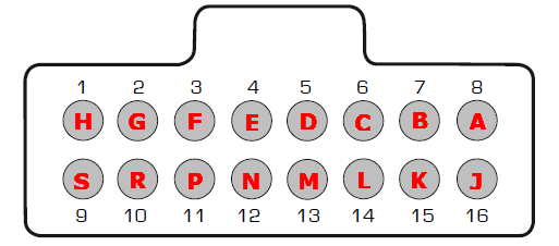
Note: Pinout is from the wiring side of the extra connector, not the terminated harness.
Pin |
Description |
Usage |
Note |
1 (H) |
+5V power supply |
|
Power supply for all +5V engine sensors |
2 (G) |
Sensor GND |
|
GND for all engine sensors, NEVER connect to engine GND |
3 (F) |
AIN 1 |
* |
|
4 (E) |
AIN 2 |
* |
|
5 (D) |
AIN 6 |
Wrong marking on some harnesses!!! |
|
6 (C) |
AIN 7 |
Wrong marking on some harnesses!!! |
|
7 (B) |
GPO 7/DIN3 |
GND output for relay control or can be used as a digital input (DIN 3) |
|
8 (A) |
GPO 5 |
GND output for relay control |
|
9 (S) |
CAN L |
|
* |
10 (R) |
CAN H |
|
* |
11 (P) |
DIN 1 |
* |
|
12 (N) |
DIN 2 |
* |
|
13 (M) |
DIN 4 |
* |
|
14 (L) |
DIN 5 |
* |
|
15 (K) |
GPO 4 |
* |
|
16 (J) |
- |
- |
|
E-Throttle/E-Pedal removal
In some cases, you want to remove the E-Throttle and E-pedal, and use a regular wire to control the throttle body.
Our solution only supports the E-Throttle, but in the above case, you need to do some wiring changes in our terminated harness.
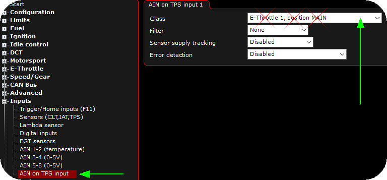
1. Disable the AIN on TPS input, set to not used.
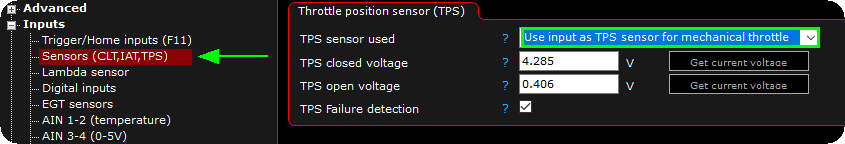
2. Set TPS sensor used to use input as TPS SENSOR FOR MECHANICAL THROTTLE.
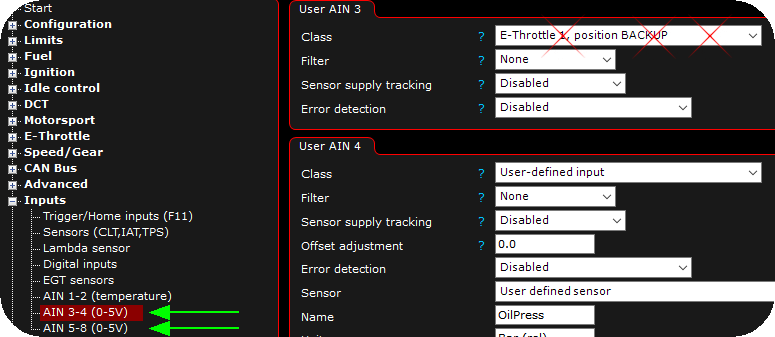
3. Disable everything that has to do with E-Throttle on the analog input channels.
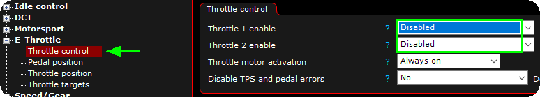
4. Make sure all E-Throttle control is disabled.
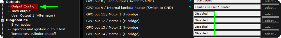
5. Finally, set all motor outputs to disabled.
E-Throttle Pin |
E-Throttle pin connector function |
MaxxECU IO |
Rewire to/note |
A |
Motor - |
CMC2: H2 |
Not used, but can instead be used to control the stock IAC |
B |
Motor + |
CMC2: H4 |
Not used, but can instead be used to control the stock IAC |
C |
Sensor GND |
CMC1: H1 |
Cut and rewire to TPS connector pin B |
D |
TPS 1 signal |
CMC1: G2 (TPS AIN) |
Cut and rewire to TPS connector pin C |
E |
+5V sensor supply |
CMC1: G1 |
Cut and rewire to TPS connector pin A |
F |
TPS 2 |
CMC1: J3 (AIN 3) |
Not used, but can be used as an extra analog input channel if needed |
E-Throttle body connector pinout in our terminated engine harness.

LS TPS Pin |
LS TPS function |
MaxxECU IO |
Rewire to/note |
A (grey) |
+5V sensor supply |
CMC1: G1 |
|
B (black) |
Sensor GND |
CMC1: H1 |
|
C (green) |
TPS signal 1 |
CMC1: G2 (TPS AIN) |
|
D |
+5V sensor supply 2 |
- |
Not used in this application |
E |
Sensor GND 2 |
- |
Not used in this application |
F |
TPS signal 2 |
- |
Not used in this application |
TPS connector pinout for most LS engines with no E-Throttle.
Extra information
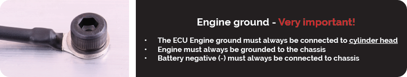
Note: Ground is important...
See also