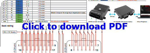
PDM20 wiring instructions in PDF format.
Note: Each PDM output pin can handle Max 10A, if you need more current, parallel wire the cables and select the same output function in MTune PDM output config.
PDM20 Max current (A)
Output |
Current (A) |
Note |
Out 1 |
25A |
+12V output |
Out 2 |
25A |
+12V output |
Out 3 |
25A |
H-bridge output (+12V or GND) |
Out 4 |
25A |
H-bridge output (+12V or GND) |
Out 5 |
25A |
H-bridge output (+12V or GND) |
Out 6 |
25A |
H-bridge output (+12V or GND) |
OUT 7 |
25A |
H-bridge output (+12V or GND) |
OUT 8 |
25A |
H-bridge output (+12V or GND) |
OUT 9 |
15A |
+12V output |
OUT 10 |
15A |
+12V output |
OUT 11 |
15A |
+12V output |
OUT 12 |
15A |
+12V output |
OUT 13 |
15A |
+12V output |
OUT 14 |
15A |
+12V output |
OUT 15 |
8A |
+12V output |
OUT 16 |
8A |
+12V output |
OUT 17 |
8A |
+12V output |
OUT 18 |
15A |
+12V output |
OUT 19 |
8A |
+12V output |
OUT 20 |
15A |
+12V output |
Max total current: 230A
Note: if total current exceeds 160A, the PDM20 needs to be mounted on a bigger heat conduction surface.
PDM20 Connector 1
Position |
Connector 1 (34-pin) |
Note |
1 |
Out 1 |
Default ECU power |
2 |
Out 2 |
|
3 |
Out 3 |
|
4 |
Out 4 |
|
5 |
Out 5 |
|
6 |
Out 6 |
|
7 |
OUT 7 |
|
8 |
OUT 8 |
|
9 |
OUT 19 |
|
10 |
OUT 1 |
Default ECU power |
11 |
OUT 2 |
|
12 |
OUT 3 |
|
13 |
OUT 4 |
|
14 |
OUT 5 |
|
15 |
OUT 6 |
|
16 |
OUT 7 |
|
17 |
OUT 8 |
|
18 |
OUT 1 |
Default ECU power |
19 |
OUT 2 |
|
20 |
OUT 3 |
|
21 |
OUT 4 |
|
22 |
OUT 5 |
|
23 |
OUT 6 |
|
24 |
OUT 7 |
|
25 |
OUT 8 |
|
26 |
CHassie GND |
|
27 |
CHASSIE GND |
|
28 |
CHASSIE GND |
|
29 |
CHASSIE GND |
|
30 |
CHASSIE GND |
|
31 |
OUT 20 |
|
32 |
OUT 20 |
|
33 |
OUT 18 |
|
34 |
OUT 18 |
PDM20 Connector 2
Position |
Connector 2 (26-pin) |
Note |
1 |
OUT 9 |
|
2 |
OUT 10 |
|
3 |
OUT 11 |
|
4 |
OUT 12 |
|
5 |
OUT 13 |
|
6 |
OUT 14 |
|
7 |
OUT 15 |
|
8 |
OUT 9 |
|
9 |
OUT 10 |
|
10 |
OUT 11 |
|
11 |
OUT 12 |
|
12 |
OUT 13 |
|
13 |
OUT 14 |
|
14 |
AIN RAW 1 (0-24V) |
Default key_in. Can be used as DIN switch with pullup enabled (15kohm to vBat). |
15 |
AIN RAW 2 (0-24V) |
Can be used as DIN switch with pullup enabled (15kohm to vBat). |
16 |
AIN RAW 3 (0-24V) |
Can be used as DIN switch with pullup enabled (15kohm to vBat). |
17 |
AIN RAW 4 (0-24V) |
Can be used as DIN switch with pullup enabled (15kohm to vBat). |
18 |
CAN L |
|
19 |
OUT 16 |
|
20 |
AIN RAW 5 (0-24V) |
Can be used as DIN switch with pullup enabled (15kohm to vBat). |
21 |
AIN RAW 6 (0-24V) |
Can be used as DIN switch with pullup enabled (15kohm to vBat). |
22 |
AIN RAW 7 (0-24V) |
Can be used as DIN switch with pullup enabled (15kohm to vBat). |
23 |
+5V SENSOR SUPPLY |
|
24 |
SEnsor GND |
To be separated from MaxxECU Sensor GND |
25 |
CAN H |
|
26 |
OUT 17 |
Part |
AMP/Superseal 1.0 |
Quantity |
Connector 1 (34-pin) |
4-1437290-0 |
1 |
Connector 2 (26-pin) |
3-1437290-7 |
1 |
Terminal / pin |
3-1447221-3 |
58 |
PDM20 wiring instructions in PDF format.