Traction control
enable
Enable or disable the traction control system.
min speed
Specifies minimum speed to enable the traction control system.
Note: the undriven wheel speed are used.
cut limitation
Enables the possibility to add a max cut in % depending on undriven wheel speed, mostly used on the lower speeds to prevent engine "stalling" when cutting to much power.
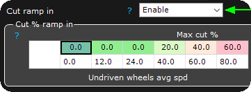
Maximum cut in % at Undriven wheel avg speed.
PID regulator
P gain
Proportional value.
I gain
Integral value.
D gain
Derivative value.
Limiter decay
When a cut % is activated, this setting specifies how fast does the cut return to 0%.
PID frequency
Specifies the PID update rate in hertz. Default 50Hz. 50 - 1000Hz.
see, PID control.
Dual PID
Used on high horse power vehicles where a faster PID is required at low speed than at higher speeds.
enable
Enable or disable the dual PID control.
P gain at high speed
Proportional value at high speed.
I gain at high speed
Integral value at high speed.
D gain at high speed
Derivative value at high speed.
low pid setpoint speed
Low Speed threshold.
High pid setpoint speed
High speed threshold.
Note: Below the low setpoint speed, it uses the lower PID settings, between the low and high threshold, the PID settings are interpolated, until the high threshold, at which only the high settings are used.
Power limiting
power limit type
Specifies how the Traction control system will reduce power to gain traction.
•Ignition cut - Most effective way of reducing engine power in the fastest way (but make sure your engine can handle such ignition cuts).
•fuel cut.
•Ignition retard + ignition cut
•Ignition retard + fuel cut
max ignition retard
Maximum ignition retard during traction control.
Retard range
The % of power cut where full retard is applied. When the retard range is maxed out, it also begins cutting power with ign/fuel drops. Normal range 20-50%.
Ex. if set to 30%, maximum retard is 30% of the above maximum ignition retard value, then ignition/fuel cut is applied.
Set to 50%
Examples
To be able to use Traction control, at least two wheel speeds must be available, using CAN input or wheel speed sensor wired to digital inputs.
In the following example we are using three wheel speed sensors, and assumes they are properly configured as Speedsensor wheelspeed front/rear right/left and calibrated.
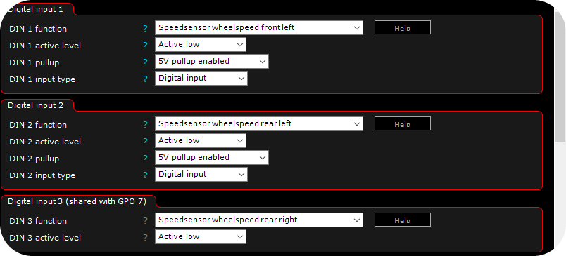
Wheel speed sensors connected and working in MaxxECU.
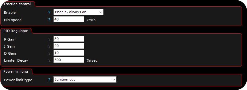
Traction --> Traction control setup settings page. Enable, always on is the preferable way of using this function, to disable it, use the digital function Disable traction.
Note: Always test and tune a traction system on a closed road/airport or similar. Power limit type Ignition cut is the most effective way of limiting power.
traction control target slip table
The traction control target slip table used by the traction control system, as all tables in MaxxECU you can select any available axis in the system, or even add 4D to the tables,

Traction --> Tractionctrl Target Slip configuration. Axis can of course be changed to almost everything available in MaxxECU. Enter your target wheel slip. 10-25% depending on tire choice is a good value to start of with.
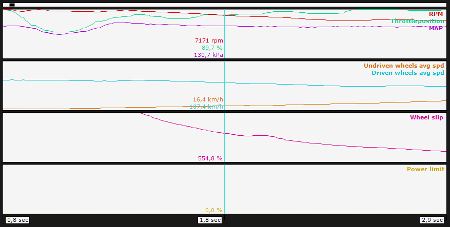
Using MaxxECU built in Live-logger (or in this case external logviewer) we can determine wheel slip (%) and power limit (%), which is calculated in realtime. In the above example the vehicle has launched, and rear wheels (Driven wheels) are spinning...
Since Undriven wheel speed are only 16,4km/h the traction system is not engaged (min speed in this example is 40km/h).
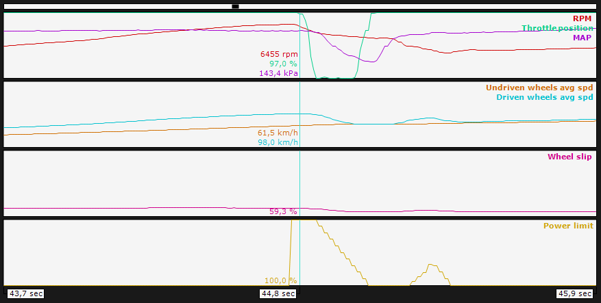
RealTime Data value Power limit in working 100% to maintain wheel slip (currently 60%).
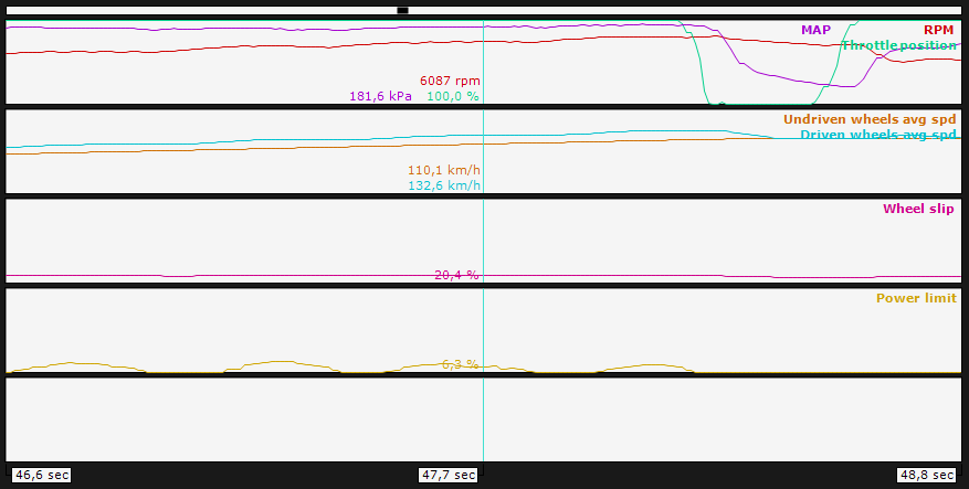
Another example of power limiting to maintain target wheel slip.
How to get faster on the run with MaxxECU
It's all about logging and testing!
1.Use a boost controller with Gear adjustment, try to achieve wheel slip target.
2.Good and properly configured Launch settings.
3.Activate Distance counters and log the run, if no access to a drag strip is available...
4.Run and log, compare RealTime Data value Power limit and Target slip. Run and log again...