The Aux Injection system controls a set of injectors separate from the regular fuel model. The injected amount is directly controlled by pulse width or duty cycle.
The injection pattern and angles are the same as the primary injectors.
This can be used to deliver extra fuel or for other purposes where a simplified fuel model is desired.
Note: The AUX system requires a wired TRIGGER to sync the event angle, it will not work if you capture for example RPM from CAN.
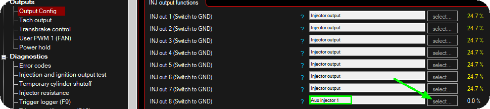
Enable the Aux system by selecting the Aux injector X output function on the wired output and the below settings will be visible under Fuel --> Aux injection in MTune.
Auxiliary injection settings
Enable
Enable or disable the aux injection system.
injection type
Specifies pulsewidth in ms or a fuel duty % to be outputted.
corrections
CLT correction
Enable to include the CLT correction (%) to the output pulse.
IAT correction
Enable to include the IAT correction (%) to the output pulse.
ASE correction
Enable to include the ASE correction (%) to the output pulse.
LAmbda correction
Enable to include the lambda correction (%) to the output pulse.
peak-hold settings
Note: The Peak-Hold settings is only workable on injector outputs on peak-hold enabled units (SPORT, RACE + PRO).
peak-hold drivers
Enables the Peak-hold drivers on the injector output used.
Note: Peak and Hold drivers MUST be enabled for low impedance(below 8ohms) injectors, and disabled with high impedance injectors (saturated).
peak current
Specifies the "peak" current which opens the injector, 3000mA = 3A which is default and used by most injectors.
Peak extension time
Only available for the GEN2 platform.
Peak extension holds the "peak" current for a fixed time before switching to "hold" current. Some injector manufacturers recommend this to ensure the injector is fully open before switching to hold current.
Use 0ms for most injectors. This minimizes heat in the injector and ECU. Use 1ms for large (300lbs/hr+) injectors at elevated fuel pressures, or when the injector manufacturer recommends a "peak hold" time.
This only affected the way the current to the injector is regulated; it does not affect the fueling.
Peak extension time Example
14ms fuel pulse with with 6A peak, 2A hold settings (same in both and below examples). (Green = Injector current, Blue = Voltage)
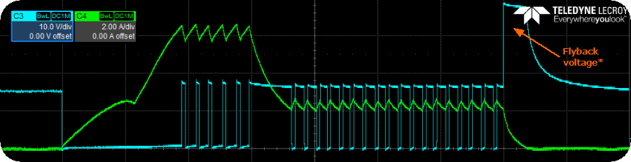
Example with a 2ms extension, the current is held at 6A for 2ms after it has reached 6A. Then it's decreased to 2A.
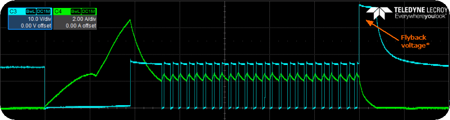
Example without an extension (0ms), the current is decreased to hold current as soon as the peak current is reached.
* Our injector drivers use a higher flyback voltage during turn-off, which forces the current in the injector coil to decay faster. This improves injector closing speed.
hold current
Specifies hold-current for injector, 1000mA = 1A works for most injectors.
injector settings
Dead time table
Injector dead time at different voltages. Deadtime is the amount of time it takes for the injector to transition from closed to open.
injector pulse width
pulse width table
The pulse width to be outputted on the selected output(s), if any corrections are applied they will be corrected using this value as the base.
injector duty
injection duty
The injector duty to be used on the output(s).