4-pin superseal connector pinout
Pin |
Description |
Usage |
Note |
1 |
+12V |
|
|
2 |
CAN H |
|
|
3 |
CAN L |
|
|
4 |
Engine GND |
|
|
Mating connector: ID 1970.
CAN wirings
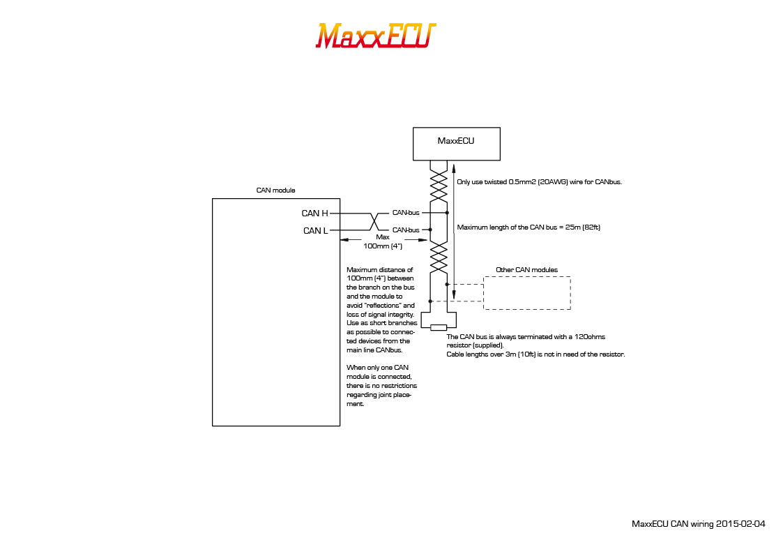
Move on to CAN Lambda Module Setup.
How to rewire and configure a LSU 4.2 prewired CAN WBO Module to be used with a LSU 4.9 sensor.
Note: Our WBO module (ID: 2038) is prewired for a LSU 4.2 sensors, if you for some reason want to use a LSU 4.9 sensor, you need to depin the LSU 4.2 connector and wire in the LSU 4.9 sensor instead.
LSU Function |
WBO module cable color |
LSU 4.2 pin |
LSU 4.9 pin |
Note |
VS |
White |
1 |
6 |
|
RCAL |
Brown |
2 |
5 |
|
+12V (H+) |
Yellow or Green |
3 |
4 |
The heater is not polarity sensitive, colors might be mixed on the WBO module here. |
H- |
Green or Yellow |
4 |
3 |
The heater is not polarity sensitive, colors might be mixed on the WBO module here. |
VREF |
Grey |
5 |
2 |
|
IP |
Pink |
6 |
1 |
Wiring chart showing the pinout differencies in LSU 4.2 vs LSU 4.9 using our WBO module.
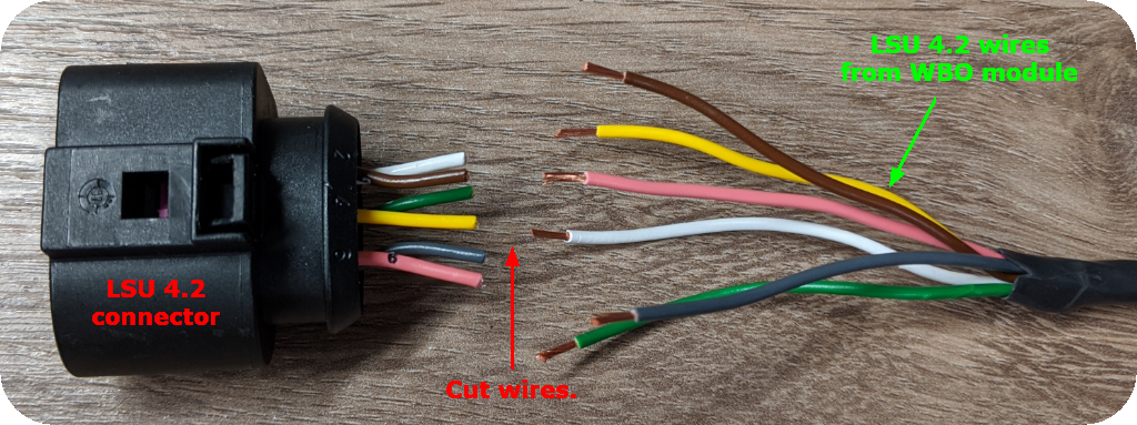
1. Cut all wires from the pre made LSU 4.2 connector.
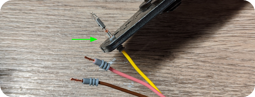
2. Use a suitable crimping tool to fasten LSU 4.9 connector terminals. Connector product ID: 1533.

3. Insert LSU 4.2 wires into the new LSU 4.9 sensor as above image.
LSU 4.2 WBO module cable color |
LSU 4.9 pin |
White |
6 |
Brown |
5 |
Yellow |
4 |
Green |
3 |
Grey |
2 |
Pink |
1 |

4. Connect power and CAN wires as explained on the top page. DO NOT CONNECT THE LSU 4.9 SENSOR YET!
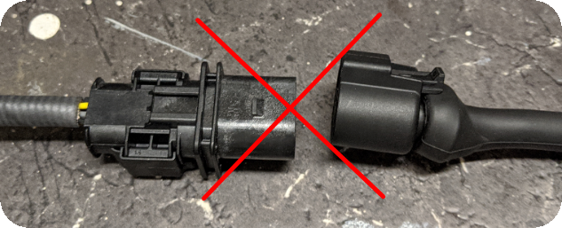
DO NOT CONNECT THE LSU 4.9 SENSOR YET! DO NOT CONNECT THE LSU 4.9 SENSOR YET! DO NOT CONNECT THE LSU 4.9 SENSOR YET!

5. Make sure the CAN WBO module is installed in the system, and be sure there is no error code related to the WBO module communication.

6. Change sensor type to LSU 4.9, and press write to module. Now the Module needs to be powered off.
7. Insert the LSU 4.9 sensor and start the WBO module.