Speed sensor
Speed source
Vehicle speed (VSS SPEED) source.
•VSS (single speed sensor, old system) - The old system and simple system, use when just a simple vehicle speed is going to be displayed on MDash or similar.
•Driven wheel speed (new system) - The new "Traction" system, use whenever you want all the new and best features related to vehicle speeds, like traction, power management, distance counters etc.
•CAN-bus (OEM protocol) - Captures wheel speed(s) from the OEM CAN Protocol (if available).
•CAN-bus (powertrain control) - Captures wheel speed(s) the enabled powertrain CAN control.
•MDash - Uses the Available GPS speed value from MDash. Use with caution.
Do NOT use the MDash option for critical functions like DCT. Loss of signal (e.g., in tunnels) can cause unexpected behavior.
sensor calibration
Speed sensors calibration with the VSS (single speed sensor, old system), press Calibrate sensor button and follow instructions.
Gear calculation
gear calculation
Specifies how the gear calculation should be made.
•Manual transmission - For manual transmissions...
•automatic transmission (ECU controlled) - for automatic transmissions that is controlled by MaxxECU.
•shiftcounter/clutch (upshift seq gearboxes only) - Used to control pneumatic/solenoid shifted drag race transmissions.
•RPM Drop (upshift sequential gearbox only) - The Gear counter by RPM drop feature increases the gear counter by sensing the decrease in RPM when the transmission is shifted. No speed sensors or position sensors are required. The counter is reset by either the Launch control, Transbrake or Clutch switch inputs. Can be used with clutchless and automatic transmissions.
•analog gear position sensor (sequential gearboxes) - Used when a gear position sensor is mounted inside sequential gearbox.
•CAN protocol (OEM) - When enabled, wheel speed source is only from any OEM CAN protocol.
transmission rpm source
•engine rpm - Use engine RPM to calculate gears (used in most cases).
•transmission input rpm sensor - use a transmission input RPM sensor to calculate gears.
gear count
Specifies the amount of forward gears in gearbox.
gear x ratio - Only available when Gear calculation = manual transmission
Gear X ratio, press Calibrate gear button when engine is around 1000rpm.
gear counter (drag transmissions)
This system is used to control pneumatic or solenoid shifted transmissions in drag race application (only up-shifting).
Each time the shift button is pressed the gear counter is increased and the shift solenoid is pulsed.
Needed inputs
•Shift button (Transmission UP shift).
•Counter reset switch from ex a Clutch switch.
counter reset source
Specifies how the gear count should be reset.
clutch reset time
The duration after which the gear counter is reset to 0 when the clutch is pressed.
clutch release to 1st delay
Time from the clutch is released to gear 1 is indicated.
Delayed gear counter UP/DOWN shift delays
Calculates the RealTime Data value Delayed Gear to be used when the instantaneous gear value VSS Gear is unsuitable for some table axes. For example shift cut gear dependencies that should be held until the shift is completed.
Gear counter delay
Specifies the amount of time to delay the RealTime Data value Delayed Gear after the VSS Gear has changed.
Note: Mostly used when you have VSS Gear as a source axis in a Shiftcut table and you want the same shiftcut time to be held until the shift is completed.
Delayed Gear example
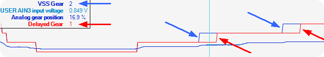
An example of the usage of delayed gear function where an delay of the actual gear change is delayed with a adjustable time.
Note: The delayed gear is NOT used to end a shiftcut operation, unless an electrical/pneumatic controlled gearbox WITHOUT analog feedback.
Analog gear position sensor
gears
Specifies the gearbox gear setup.
•R+N+4
•R+N+5
•R+N+6
Between gears
Specifies how the VSS GEAR RealTime Data value will be updated.
•Indicate neutral between gears
•keep last value until next gear is engaged
X gear setup
Used to calibrate all gears by pressing the Get current value button and enter min and max range on each gear.
X gear sensor value
The current value from the gear position sensor, press Get current value button for calibration.
X gear min range
Specifies the MIN range from the above GEAR sensor value for the system to consider this gear is in position.
X gear max range
Specifies the MAX range from the above GEAR sensor value for the system to consider this gear is in position.
If the 1st Gear sensor value is 20%, min range is 4% and Max range is 6%, the system will consider the 1st gear to be in position when the gear sensor value is between 16 to 26%.
min rpm drops
Used when the Gear Calculation = RPM Drop (upshift sequential gearbox only).
Increases the gear counter by sensing the decrease in RPM when the transmission is shifted. No speed sensors or position sensors are required. The counter is reset by either the Launch control, Transbrake or Clutch switch inputs. Can be used with clutchless and automatic transmissions.
RPM drop gear x -> Y
Specifies the amount of RPM drop needed to trigger the gear increase.
min time to next shift
time to next shift after x->y
Specifies the time after the last shift during which RPMs above the shift threshold is ignored. Used to prevent the gear counter from increasing twice in case of wheel slip or slow shifting.
Some gearboxes (especially sequential ones) are equipped with an analog gear position sensor which gives an 0-5V output signal to represent the "in gear position".
Example
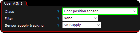
1. Enable the gear position sensor on the wired analog input channel.
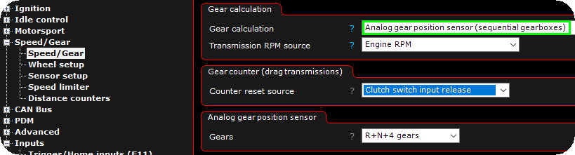
2. Change the Gear calculation to analog gear position sensor (sequential gearboxes), and change all settings to suit your need.
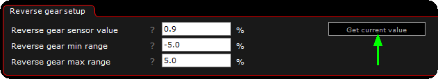
3. Calibrate all gears by pressing the Get current value button and change the min and max range to suit your need.
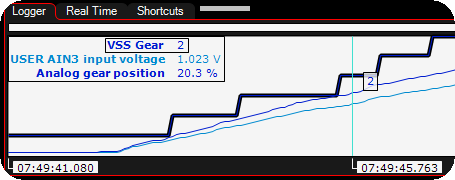
4. After the calibration is made, make sure the VSS GEAR do change as it should in the system in relation with the analog gear position (%).