keypad settings
Keypad
Select the CAN keypad you have installed.
Note: Currently we support the RACEPAD, CAN PRO keypads, 4, 6, 8,12 and 15 key from Blink Marine.

The below is only available for PDM keypads.
backlight control
•Always on - The backlight is always on, programmed at Keypad setup.
•on/off with ignition on (no off delay) - The backlight is turned off when ignition key is OFF.
•on/off with ignition on (1 min off delay) - The backlight is turned off after 1 minute when an ignition key OFF event is detected.
•on/off with ignition on (5 min off delay) - The backlight is turned off after 5 minutes when an ignition key OFF event is detected.
backlight level, lights off
Specifies the background light level when lights is OFF.
backlight level, lights on
Specifies the background light level when lights is ON.
Note: 0-63, where 63 is the brightest, listens to the digital inputs functions: Lights, low beam, Lights, high beam and Lights, park.
button settings
Description
Assign a descriptive name to the output or function. This name is displayed throughout MTune PC-software and MDash Android app, making it easier to identify and distinguish the function in configuration menus, monitoring views, logs, and dashboards. Use clear, meaningful names.
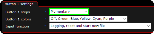
button steps
Sets the type of switch to be used.
•Not used/used by other ECu/PDM.
•MOMENTARY - Shifts Button state between ON (1) and OFF (0). Only ON (1) when the switch is press and hold.
•2 positions - Shifts Button state between 0 and 1.
•3 positions - Shifts Button state between 0, 1 and 2.
•4 positions - Shifts Button state between 0, 1, 2 and 3.
•5 positions - Shifts Button state between 0, 1, 2, 3 and 4.
•6 positions - Shifts Button state between 0, 1, 2, 3, 4 and 5.
Keep state
Specifies how the button state is handled after a power cycle.
•Keep last state when power is lost - Restores the button to its previous state when power is reapplied.
•reset to off when power is lost - Forces the button to the OFF state whenever power is restored.
Encoder settings
Description
Defines the name or description of the encoder, used for identification.
encoder type
Enable control of the encoder from this ECU/PDM. An encoder can only be controlled from one ECU/PDM.
steps
Defines the number of steps for the rotary encoder (0–255).
led pattern
Defines which LED pattern to use. Options: Single LED, Bar graph, or One + first/last.
led offset
Used to adjust the LED direction depending on which direction the PKP350 keypad is mounted.
Functions
input function (s)
The Digital input function to trigger when the current switch changes state from 0.
Note: A later update will include to trigger different digital input function based on the switch state above 0 and 1, for now use the internal output.
Button LED
button state colors
Sets the colors to be used depending on the current switch state.
•off, green, blue, yellow, cyan, purple.
•red, green, blue, yellow, cyan, purple.
•Not used.
fault indication
Option to blink the button in red to indicate any, or specified fault.
User color 1/2
Option to set a certain keypad button color upon user condition.
Examples

The above example will use the default color Red on the switch when nothing is pressed, but when pressed it will light up Green, change to boost level 2 and stay Green until pressed again.
The above example will change the switch state ONLY when the button is pressed, during key press, MaxxECU will start logging (if ECU loggings is set to input switch) and colored Green during press.