Note: Your VIN must be entered in MTune to be broadcasted on the bus, see here for more information on the Mustang OEM CAN protocol.
Vehicle cover list
Vehicle |
Engine code |
Year |
LSU sensor |
Note |
Ford Mustang GT V8 |
Coyote |
2011-2014 |
Uses stock LSU 4.9 WBO sensors |
The LSU 4.9 WBO sensors do not work well with launch/anti-lag functions, be aware. |
Note: Manual transmission only!
Control options
Only available as a MaxxECU PRO solution.
OEM options |
MaxxECU IO |
MaxxECU PRO |
Note |
Generator (PWM) control |
GPO 1 |
Yes |
|
Fuel pump (PWM) control (stock pump) |
GPO 2 |
Yes |
|
EVAP |
GPO 3 |
Yes |
|
EVAP purge valve |
GPO 4 |
Yes |
|
FAN (Low) |
GPO 5 |
Yes |
|
FAN (High) |
GPO 6 |
Yes |
|
E-Throttle |
GPO 11/12 |
Yes |
|
Injectors (sequential) |
INJ 1 - 8 |
Yes |
|
Ignition (sequential, COP) |
IGN 1- 8 |
Yes |
|
VCT solenoid 11 (right intake) |
GPO 23 |
Yes |
|
VCT solenoid 21 (left intake) |
GPO 24 |
Yes |
|
VCT solenoid 12 (right exhaust) |
GPO 25 |
Yes |
|
VCT solenoid 22 (left exhaust) |
GPO 26 |
Yes |
|
Oil pressure meter (dash) |
GPO 27 |
Yes, read note |
Wired, but not implemented |
AC compressor (ACCR) |
GPO 29 |
Yes |
|
CHT (Coolant temp sensor) |
CLT |
Yes |
|
Intake air temp (external) sensor |
IAT |
Yes |
|
MAF (stock with IAT) |
- |
Stock MAF must be removed and replaced with the built-in MAP sensor, a external IAT should be mounted. |
|
Crank trigger (60-2) |
TRIGGER |
Yes |
|
CAM pos 12 (left exhaust) |
HOME |
Yes |
|
CAM pos 11 (right intake) |
DIN 1 |
Yes |
|
CAM pos 22 (left exhaust) |
DIN 2 |
Yes |
|
CAM pos 21 (left intake) |
DIN 3 (GPO 7) |
Yes |
|
OSS signal |
DIN 4 |
Yes |
|
Clutch input |
DIN 5 |
Yes |
|
Low oil level switch |
DIN 8 |
Yes, read note |
Wired, but not implemented |
Cruice control SCCS |
AIN 9 |
Yes, read note |
Wired, but not implemented |
AC pressure |
AIN 13 |
Yes |
|
Tachometer |
Yes |
||
Knock sensors (OEM) |
KNOCK1/KNOCK2 |
Yes, read note |
Wired, but not used |
Individual wheel speed (all) |
Yes |
||
Engine warning light |
Yes |
||
Speedometer |
Yes |
||
Traction light |
Yes |
||
Odometer |
Yes |
||
Fuel consumption |
- |
||
AC button |
Yes |
||
Traction on/off |
Yes |
Using MaxxECU built-in traction control system |
|
Bluetooth (MDash) |
|
- |
|
EGT option |
EGT 1 - 8 |
Yes, direct |
8 EGT direct in harness |
16-pin extra connector
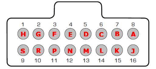
Note: Pinout is from the wire side of the supplied connector.
Pin |
Description |
Usage |
Note |
1 (H) |
AIN 1 |
|
|
2 (G) |
AIN 2 |
|
|
3 (F) |
AIN 3 |
|
|
4 (E) |
AIN 4 |
|
|
5 (D) |
IAT |
|
Connect an external IAT for boosted application here |
6 (C) |
DIN 7 |
|
|
7 (B) |
CAN 2 High |
|
|
8 (A) |
CAN 2 Low |
|
|
9 (S) |
GPO 28 |
|
|
10 (R) |
GPO 30 |
- |
|
11 (P) |
Ignition key (+12V) |
Output at ignition on |
+12V output (ignition key) |
12 (N) |
+12V power supply |
Output at ignition on |
+12V output |
13 (M) |
Engine GND |
- |
|
14 (L) |
- |
- |
|
15 (K) |
Sensor GND |
|
|
16 (J) |
+5V sensor supply |
|
Plugin adapter description
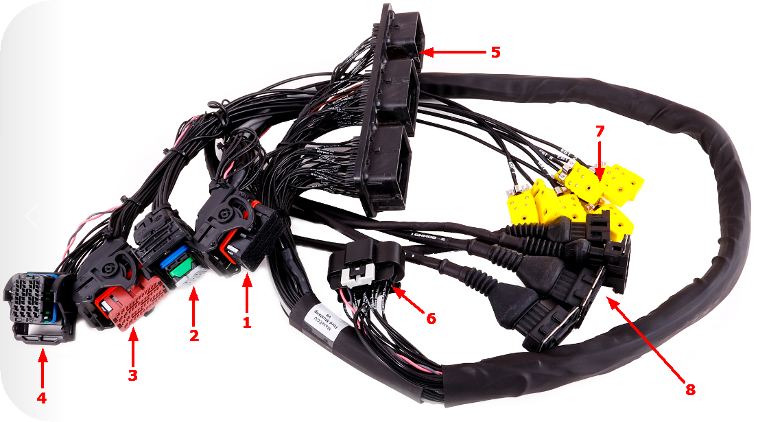
1 |
MaxxECU CMC connector 1 |
2 |
MaxxECU CMC connector 2 |
3 |
MaxxECU CMC connector 3 |
4 |
MaxxECU CMC connector 4 |
5 |
Vehicle harness adapter |
6 |
16-pin extra connector |
7 |
EGT connectors (1-8) |
8 |
Ignition module connectors (x4) |
Note: The vehicle harness ECU connector (5) is from old/used ECUs from scrapyards because we couldn't find new ones.
ECU location and installation
Stock ECU is located in engine bay, on the right side in the front of the engine.
1.Disconnect battery from vehicle.
2.Remove and disconnect stock ECU from vehicle harness.
3.Depending on your installation you might need to reroute your engine harness connector (in case you have a big turbo in the way or similar).
4.Install MaxxECU adapter harness.
5.Route the included MaxxECU MAP sensor hose to the intake manifold and connect into the MaxxECU.
6.Optionally install a intake air temperature sensor (IAT) which is recommended (especially on boosted applications) and connect to MaxxECU.
Optional: Install external intake air temperature (IAT) sensor
Some vehicles are not equipped with an intake air temperature (IAT) sensor and MaxxECU plugin solutions do have the
option to add a sensor.
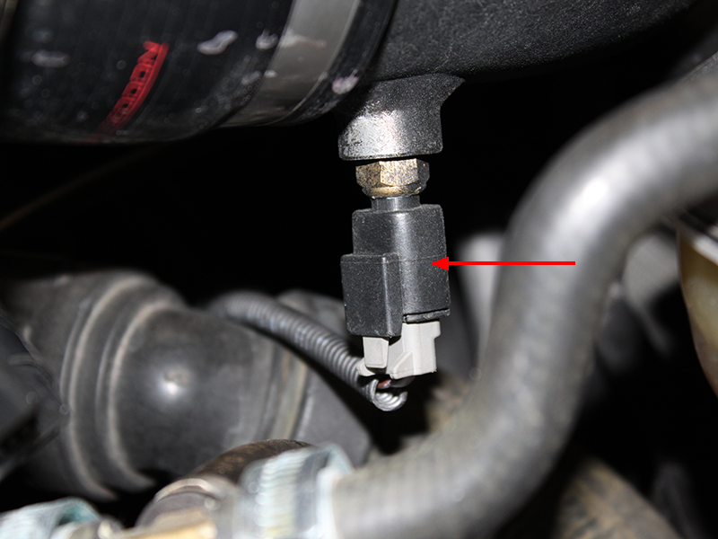
The intake air temperature (IAT) sensor should be mounted to sense fresh air flow going into the engine.
Depending on the intake manifold construction, the position of the temperature sensor is not given, but preferably mount
the sensor in the intake, or in the pipe before/after the throttle.
IAT wiring
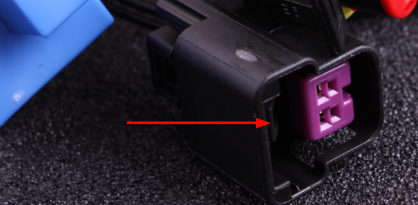
MaxxECU plugin solution are equipped with an optional 2-pin connector for optional IAT wiring.
Mating connector and wires for external IAT sensor.
See also
Example wirings of extra input and output