The MaxxECU CAN WBO module is a single CAN module which enables the usage of up to 8 more individual wide band lambda sensors in the system on ANY MaxxECU.
Note: Each module can handle one lambda sensor, to get 8 extra lambda sensors on any MaxxECU, you need 8 CAN WBO modules.
Module id/package setup
Module ID
The module ID to program on the ONLY installed CAN Module.
Note: Only ONE module can the attached in the system simultaneously during programming, otherwise all modules will get the same module ID, and that will cause all kind of strange problems...
Package type
•MaxxECU default - Send all data needed for diagnostics and normal operations.
•MaxxECU reduced - Sends a reduced data-package without advanced operation parameters. Can be used to reduce bus-load.
sensor type
Specifies which LSU sensor (4.2/4.9) attached to the module.
•LSU 4.2
•LSU 4.9
Be sure to repin the WBO module LSU connector to the correct sensor pinout, found here: CAN Lambda Module wiring.
Note: The module must always be restarted when you disconnect the LSU sensor.
Enable and program the MaxxECU CAN WBO module.
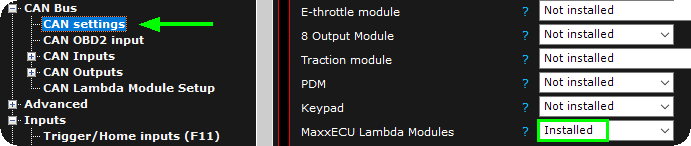
1. Active the CAN WBO Module in MTune settings, CAN Bus --> CAN settings, Installed modules.
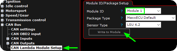
2. Change the Module ID, package type and sensor type to suit your need, then click write to module.
Note: Each module must have an unique ID number. All modules are delivered set to ID 1. If you are using 2 or more modules you need to change the ID of those. If you only have a single module, you can skip this step.
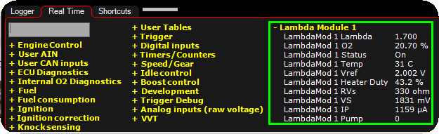
3. Available RealTime Data values in the system when a WBO CAN Module 1 is installed in the system.
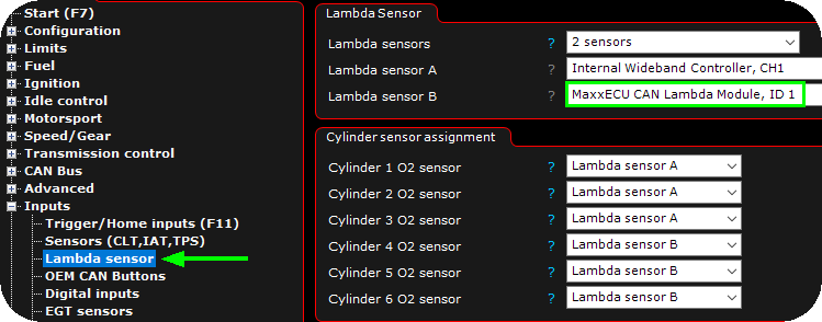
4. In the above example, we are using a MaxxECU RACE which only have one single WBO controller built-in, but with the CAN WBO Module installed we get access to a second WBO in the system when we install it as a MaxxECU CAN Lambda Module, ID 1.
Note: Dont forget to do the correct cylinder sensor assignment, otherwise Lambda control will behave very strange...
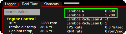
5. Available in the system now is two Lambda values according to the settings in the above step.
CAN communication
Note: For any other CAN module manufacturer who wants to implement our protocol.
Optional, ECU->Modules
ID: 0x1AA521C0
DLC: 1
Byte 0: Lambda enabled
(0 = off, 1 = on, heating starts)
This message is optional. If it's not sent the sensor is on by default.Module->ECU:Base IDs.
0x180 CH1
0x185 CH2
0x18A CH3
0x18F CH4
0x194 CH5
0x199 CH6
0x19E CH7
0x1A3 CH8
ID: BaseCANID + 0
DLC: 8
Little endian. 0-1 Lambda, scale 0.001 lambda
Byte 2-3 O2 %, scale 0.01 %
Byte 4-5 Status bits
Byte 6-7 Not usedBits
0 Lambda Active (module enabled, may not be up to temperature yet, wait for warmup bit and all error bits to be 0 before using the values)
1 Warming up
2 Not used
3 Error, Vref
4 Error, Pump
5 Error, Warmup failed
6 Error, Sensor too cold
7 Error, Sensor too hotOptional values (used only for logging)
These can be turned off and is not necessary for the ECU.
ID: BaseCANID + 1
DLC: 8
Little endian.
0-1 Module temperature, 1C
2-3 Not used
4-5 VREF voltage, 1mV
6-7 Heater Duty 0.1%ID: BaseCANID + 2
DLC: 8
Endian: Big
0-1 RI 1ohm
2-3 VS 1mV
4-5 IP measured 0.001mA
6-7 Pump Drive signal 0-4095