Alternator voltage control
Voltage control
Enables or disables the output voltage control duty.
Output type
Sets the output type, normal or inverted signal duty.
•Normal, high duty = high power
•inverted, low dUty = high power
Target voltage
The target alternator voltage (V).
PWM frequency
PWM frequency (Hz) to use on the output. <-- Make sure to use the correct frequency of your alternator by checking with the manufacturer.
P gain
P-value in the PI control regulation.
I gain
I-value in the PI control regulation.
Min control duty
Minimum duty to be applied to the output.
max control duty
Whether to use a fixed value or use a table to limit the max output duty, set to table and limit the max duty with the engine run-time axis to limit the alternator from stalling the engine directly on start-up.
Example
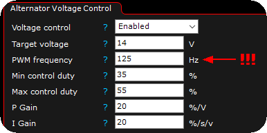
The above is an example to control the Ford Coyote 5.0 alternator, working at 120Hz, but MAKE SURE TO ENTER YOUR ALTERNATORS CORRECT FREQUENCY. <-- To low frequency can cause sever damage on your engine and/or alternator.
PID control
PID is a "closed loop" control algorithm (instructions for solving a task) used to adjust a control value, (eg a idle valve position). In order to process actual values (eg engine speed ) to match the desired TARGET value (eg, idle speed ) then adjusts the PID-algorithm control value according to these three elements.
Summary
P is used to bring the value close to the target.
I is used to bringing the error to zero.
D is used to dampen the response.
Setup process
P and I must always be used (not allowed to be zero), D is optional and not always necessary.
•Usually starting by increasing the P and I together (using the same values) until it becomes slightly unstable.
•Bring in some D to counteract that, and then fine-tune each value. Often by reducing P and increasing I.
•The overall goal is to use as high values as possible while still having a stable response.
•Then decrease all values a bit to add some safety margin to prevent overshoot or oscillation.
Typical problems (P)
•Too low: Does not reach target, slow response.
•Too high: Fast oscillation.
Typical problems (I)
•Too low: Does not reach the target, slow response, overshoots and recovers slowly.
•Too high: Oscillation.
Typical problems (D)
•Too low: Overshoot.
•To high: Oscillation.
Example
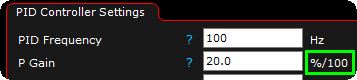
The above "%/100" means % per 100 error.
Example: 100 error --> 100% duty outputed.